Thermal Print Head and Method for Manufacturing the Same

Active Publication Date: 2007-10-04
ROHM CO LTD
View PDF0 Cites 6 Cited by
  • Summary
  • Abstract
  • Description
  • Claims
  • Application Information

AI Technical Summary

Benefits of technology

[0010] The present invention is proposed under the above-described circumstances. It is therefore an object of the present invention to provide a thermal printhead and method for manufacturing the same, for preventing disconnection of the resistor, for enhancing heat transfer efficiency from the heating portion of the resistor to the thermal recording medium, and for smooth transfer of the thermal paper. MEANS FOR SOLVING THE PROBLEM

Problems solved by technology

As a result, the print density is lowered and thus poses difficulty in the high-quality printing as well as the high-speed printing.
In the irregularities, there is a tendency of accumulation of ink of an ink ribbon for thermal recording or of paper particles of thermal paper.
Further, transfer of the thermal recoding medium cannot be performed smoothly in contact with the surface of the protection layer 94.

Method used


Image

  • Thermal Print Head and Method for Manufacturing the Same
  • Thermal Print Head and Method for Manufacturing the Same
  • Thermal Print Head and Method for Manufacturing the Same

Examples


first embodiment

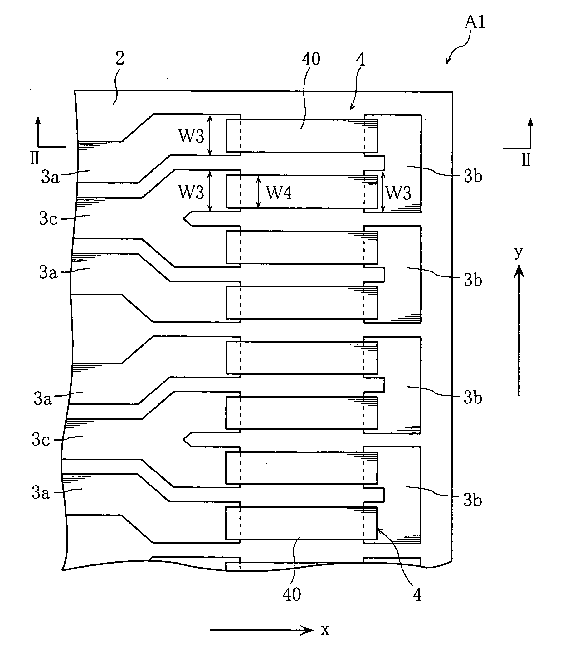
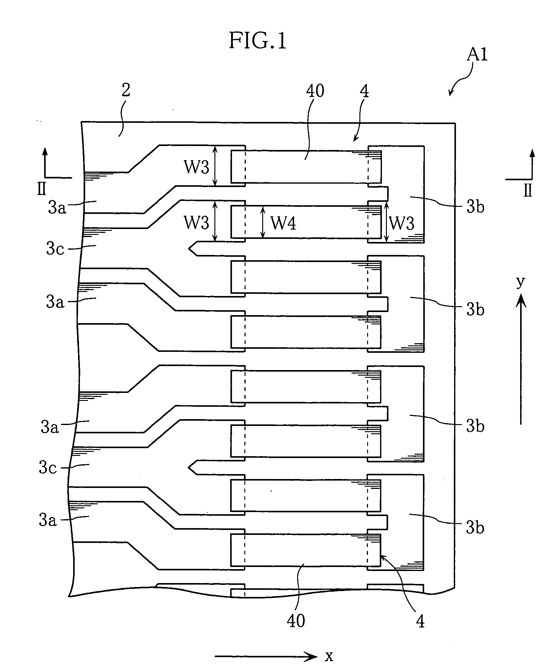
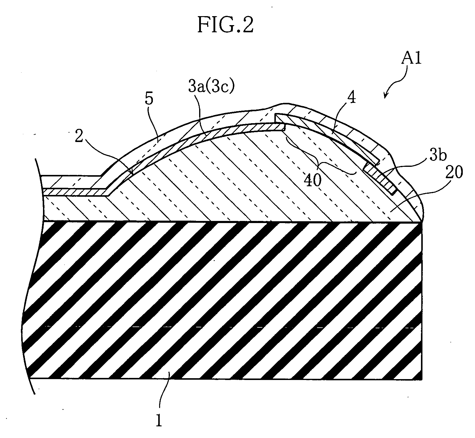
[0060]FIGS. 1 and 2 illustrate a thermal printhead according to the present invention. The thermal printhead A1 of the embodiment includes a substrate 1, glaze layer 2, a plurality of electrodes 3a-3c, a plurality of resistors 4, and a protection layer 5. In FIG. 1, the protection layer 5 is omitted.

[0061] The substrate 1 is a flat rectangular insulating substrate made of ceramic, and extends in the primary scanning direction y. The glaze layer 2 is formed on the substrate 1 by printing and baking an amorphous glass paste, and serves to enhance the heat reservation and to smooth the surface which is to be formed with the plurality of electrodes 3a-3c. The glaze layer 2 has a projection 20 having a convex surface. The projection 20 serves to increase the contact pressure between portions of the protection layer 5, corresponding in position to heating portions 40 described below, and a thermal recording medium such as ink ribbon and thermal paper.

[0062] The electrodes 3a-3c are forme...

second embodiment

[0101] As shown in FIG. 25, each of the bonding pads 32 includes a first portion 32a partly overlapping with a second portion 32b. The bonding pad is identical to the second embodiment in that the first portion 32a has an upper surface flush with the surface of the glaze layer 2, and the second portion 32b protrudes out of the glaze layer 2. The common electrode 3e includes one belt-like portion 36.

[0102] With such structure, the wire W can be properly bonded, and the bonding strength between the wire W and the bonding pad 32 can be increased. Further, as the area of the first portion 32a is reduced, gold material can be saved.

[0103] Next, an example of manufacturing method of the thermal printhead A3 is described with reference to FIGS. 26-29. FIGS. 26-29 are sectional views illustrating a series of steps in the manufacturing method of the thermal printhead A3 according to the present embodiment.

[0104] In the manufacturing method of the present embodiment, as already described wi...


PUM


Abstract

A thermal printhead (A1) includes electrodes (3a-3c) embedded in a glaze layer 2 at least at a portion laminated with a resistor (4). Favorably, the portion of the electrodes (3a-3c) laminated with the resistor (4) is sunk to a depth causing the surfaces of the electrodes to be flush with the surface of the glaze layer 2. Such structure enhances the heat transfer efficiency from a heating portion (40) of the resistor (4) to a thermal recording medium, and smooth transfer of thermal recording paper.

Description

TECHNICAL FIELD [0001] The present invention relates to a thermal printhead and method for manufacturing the same. BACKGROUND ART [0002]FIGS. 30 and 31 illustrate conventional thermal printheads. The thermal printhead X1 includes an insulating substrate 90, a glaze layer 91, a resistor 92, electrodes 93a, 93b, and a protection layer 94 laminated in the mentioned order (see Patent Document 1, for example). Theresistor 92 includes a heating portion 92a arranged between the electrodes 93a, 93b. The heating portion 92a generates heat which enables printing on a thermal recording medium. [0003] In manufacturing the thermal printhead X1, the electrodes 93a, 93b are formed after the formation of the resistor 92. Formation of the electrodes 93a, 93b is performed by printing and then baking resinate gold paste on the resistor 92. Due to the heat for the baking, the resistor 92 may be oxidized into alteration. [0004] To solve this problem, the resistor 92 and the electrodes 93a, 93b of the th...

Claims


Application Information

Patent Timeline
IPC IPC(8): B41J2/335
CPCB41J2/33515B41J2/3351B41J2/32B41J2/335
Inventor YAMAMOTO, MASAYAOBATA, SHINOBU
Owner ROHM CO LTD
Why Eureka
Try Eureka