

Actuator ball retriever and valve actuation tool
a technology of actuator balls and actuator balls, which is applied in the field of tools, can solve the problems of reducing the number of valves in the well, affecting the operation of the valve, and requiring expensive drilling procedures to remove the actuator balls
- Summary
- Abstract
- Description
- Claims
- Application Information
AI Technical Summary
Benefits of technology
Problems solved by technology
Method used
Image

Examples
Embodiment Construction
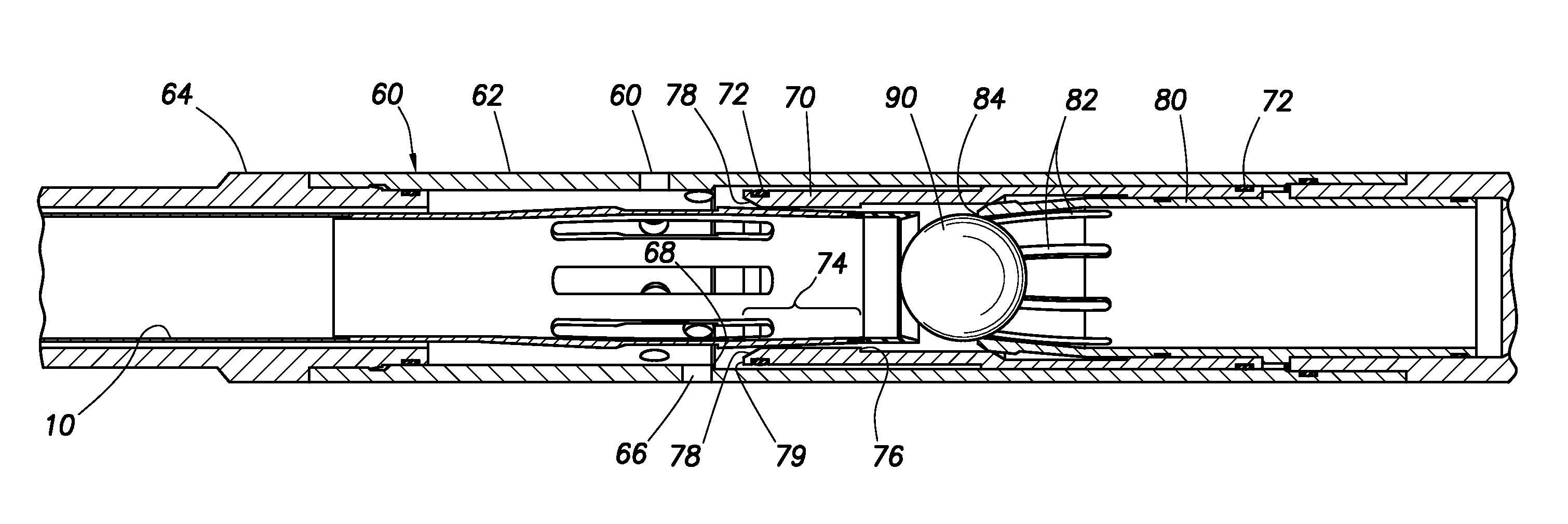
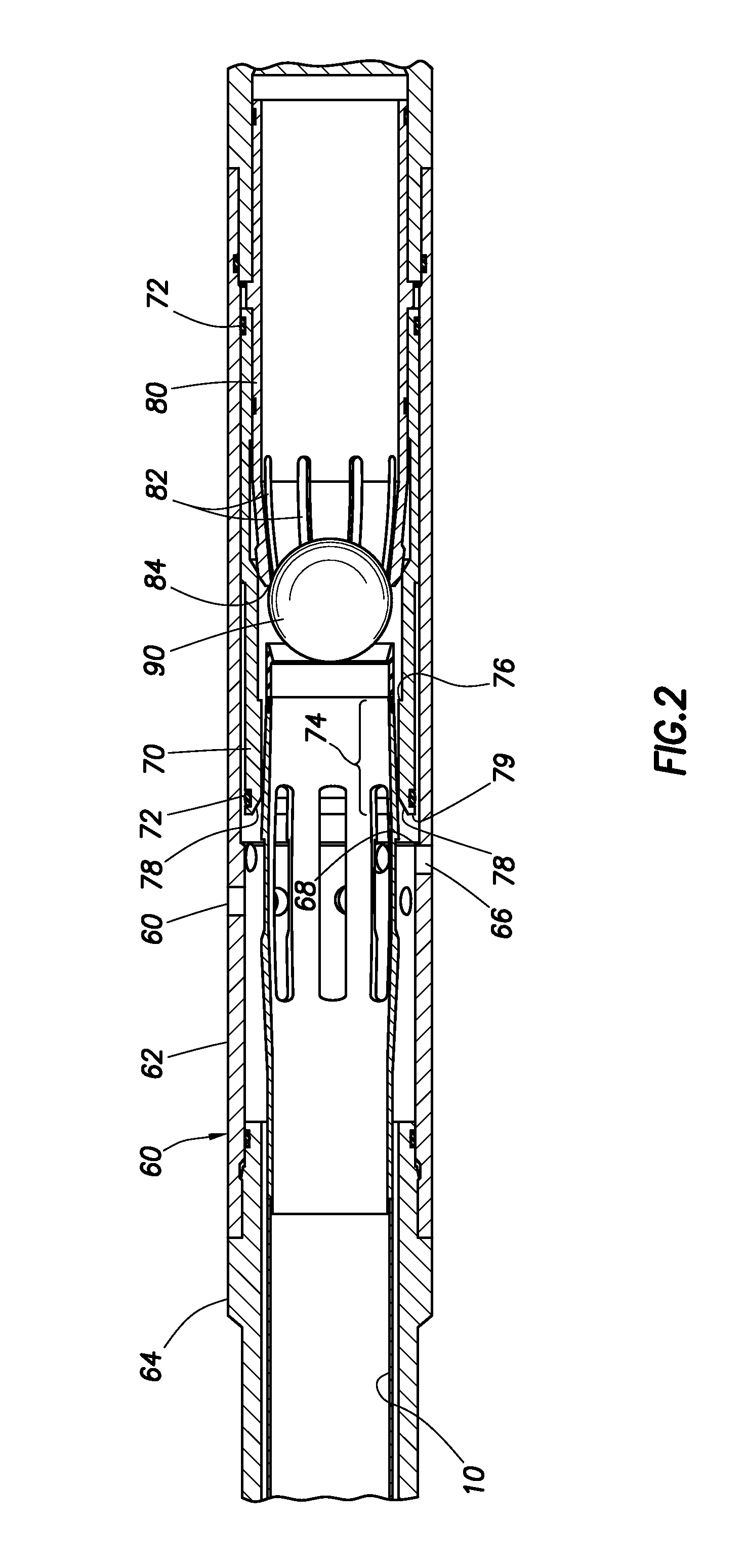
[0012]The present invention provides an improved tool and method for retrieving actuator balls and engaging and shifting elements of the valves. The present invention's particular applicability is to multiple sleeve wellbores that are actuated by balls of the same diameter.
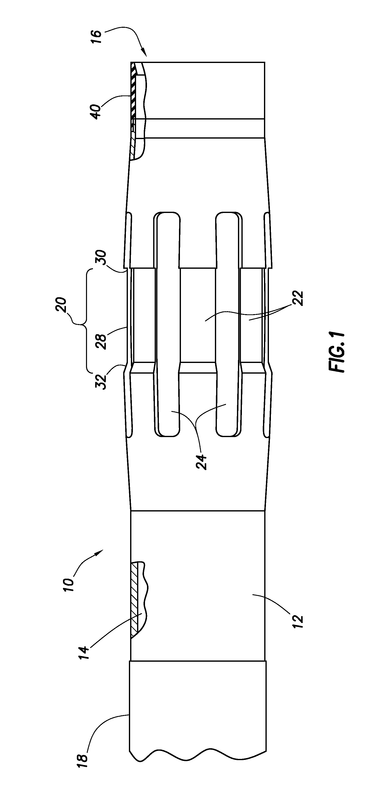
[0013]Referring more particularly to the drawings, wherein like reference characters are used throughout the various figures to refer to like or corresponding parts, there is shown in FIG. 1 one embodiment of the tool 10 of the present invention which is adapted to be lowered into a wellbore while connected to a wire line or tubular string. It should be understood by those skilled in the art that the use of directional terms, such as above, below, upper, lower, upward, downward and the like are used in relation to the illustrative embodiments as they are depicted in the figures, the upward direction being toward the left side of the corresponding figures and the down-hole direction being toward the right side of t...
PUM
 Abstract
Description
Claims
Application Information