Coupling for a belt tensioner

a belt tensioner and belt tensioning technology, which is applied in the direction of mechanical actuator clutches, mechanical equipment, transportation and packaging, etc., can solve the problems of non-uniform force transmission to the driven element, and achieve the effect of preventing disturbing nois

Active Publication Date: 2014-10-30
TRW AUTOMOTIVE GMBH
View PDF6 Cites 5 Cited by
  • Summary
  • Abstract
  • Description
  • Claims
  • Application Information

AI Technical Summary

Benefits of technology

[0019]Preferably, a reset spring for biasing and de-rattling the control element in the direction of the home position is provided between the drive member and the cont

Problems solved by technology

It is a drawback of those clutches that a control ensuring simultaneous engagement of all pawls is required.
When the pawls are not synchr

Method used


Image

  • Coupling for a belt tensioner
  • Coupling for a belt tensioner
  • Coupling for a belt tensioner

Examples


Embodiment Construction

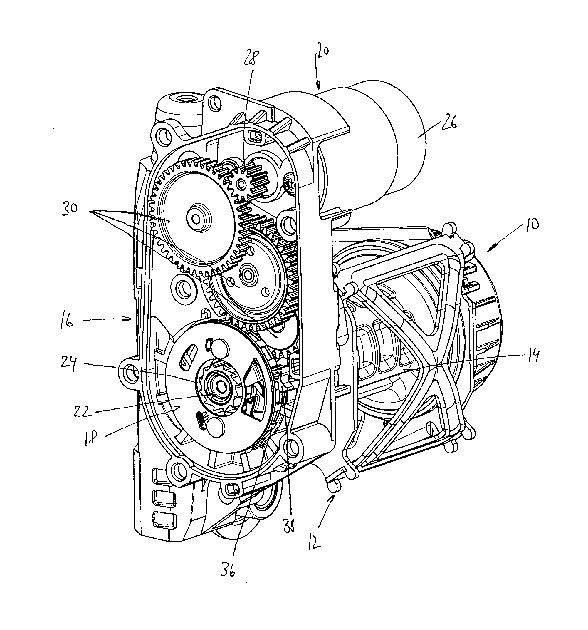
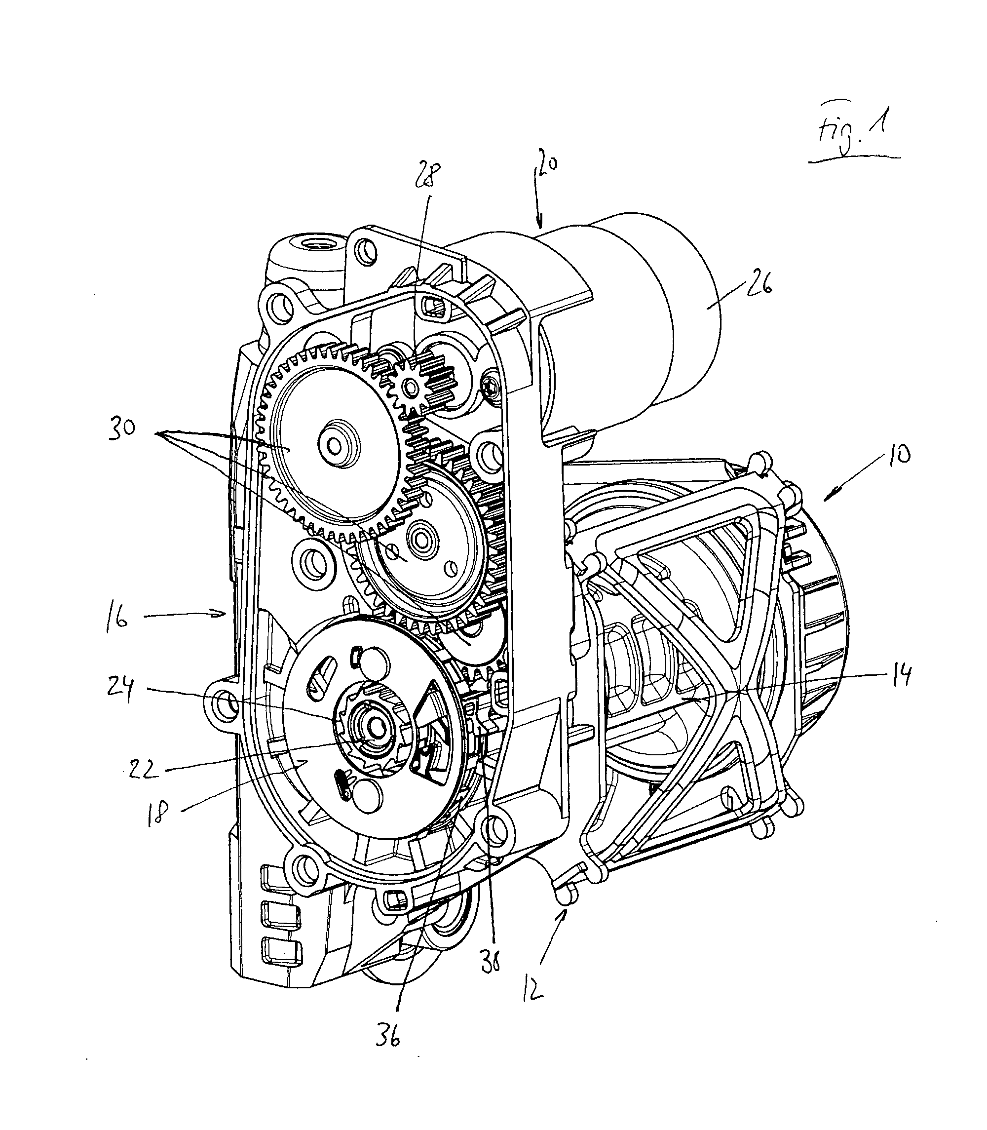
[0027]In FIG. 1 a belt retractor 10 for a seat belt is illustrated. The belt retractor 10 comprises a housing 12 in which a belt reel 14 for a seat belt is arranged and on which a belt tensioner 16 is disposed. The belt reel 14 is pivoted in the housing 12 and can be coupled to the drive 20 of the belt tensioner 16 by a clutch 18 shown in detail in FIGS. 4 to 6 and can be rotated in a winding direction A so as to wind up the seat belt on the belt reel 14. For this purpose, a stub shaft 22 of the belt reel projects through the housing 12. A toothing 24 is fixedly mounted on said stub shaft. In the embodiment illustrated here the toothing 24 at the same time forms the driven element of the clutch.

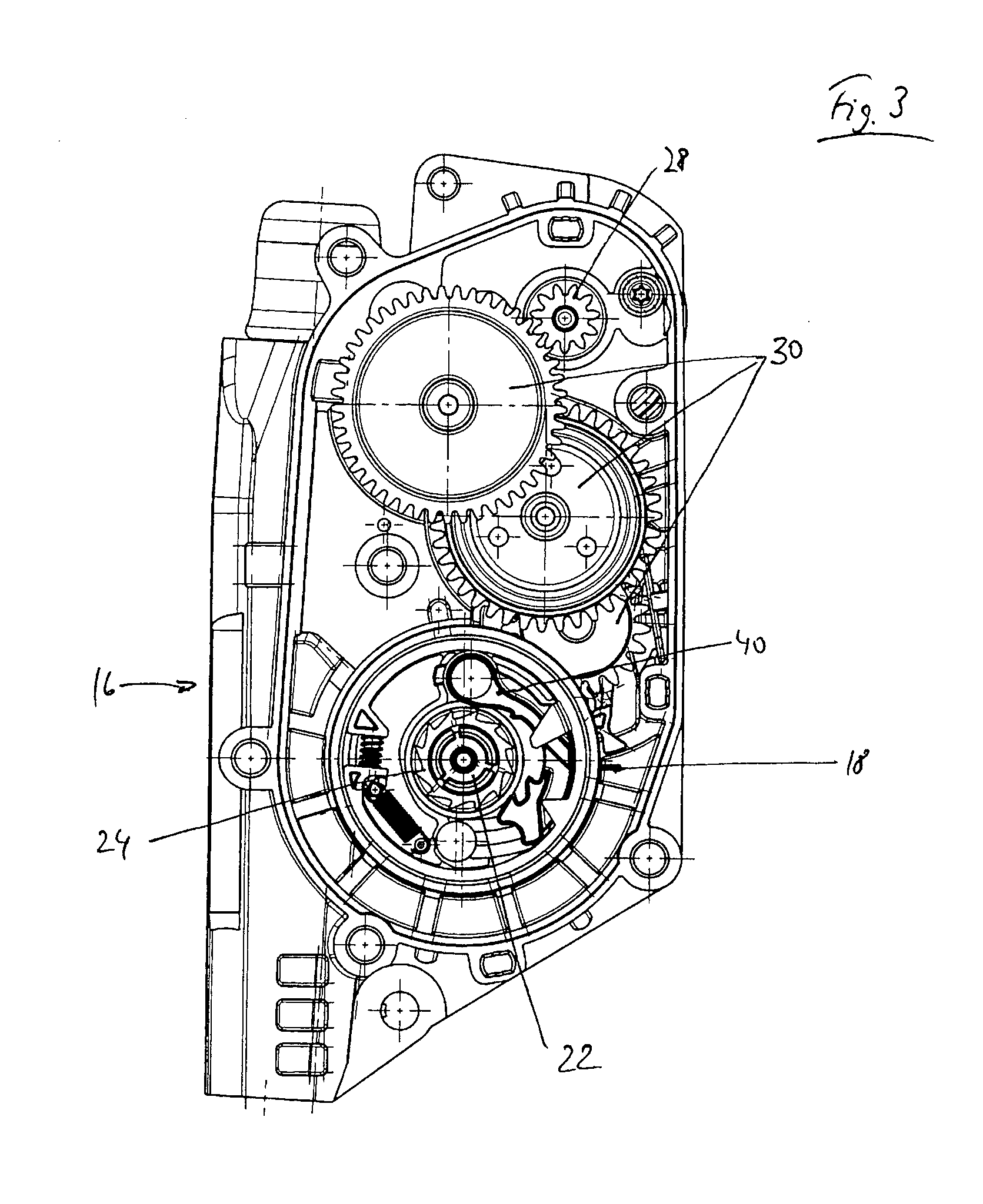
[0028]The drive 20 of the belt tensioner 16 includes a drive motor 26 having a motor gearwheel 28 coupled to a spur gear system 30. Said spur gear system 30 is coupled to the belt reel 14 via the clutch 18.

[0029]The input side of the clutch 18 is formed by a clutch support 32 connected to an ...


PUM


Abstract

A controllable clutch (18) for a belt tensioner (16) comprises a drive member (32), a driven element (24) and a clutch pawl (40) that is movably supported on the input side (30) between a home position and an engaged position and in the engaged position couples the drive member (32) to the driven element (24), wherein the clutch pawl (40) is tension-loaded in the engaged position.

Description

RELATED APPLICATIONS[0001]This application corresponds to PCT / EP2012 / 004802, filed Nov. 20, 2012, which claims the benefit of German Application No. 10 2011 119 343.3, filed Nov. 25, 2011, the subject matter, of which are incorporated herein by reference in their entirety.BACKGROUND OF THE INVENTION[0002]The invention relates to a controllable clutch for a belt tensioner, especially a reversible belt tensioner.[0003]Reversible belt tensioners include a drive adapted to be coupled to the retractor axle of a belt reel by means of a clutch. During regular operation of the belt retractor the belt reel is uncoupled from said drive so that retracting or unwinding of the webbing from the belt reel is possible. In the case of tensioning the clutch is coupled to the belt reel by activation of the drive so that the webbing is wound onto the belt reel and thus is retracted.[0004]Usually the clutch comprises a driven member having a toothing and being adapted to be coupled to a drive member via...

Claims


Application Information

Patent Timeline
IPC IPC(8): F16D41/12
CPCF16D41/12B60R22/46B60R2022/4666B60R2022/468B60R2022/469
Inventor NUDING, MARTINHOLBEIN, WOLFGANG
Owner TRW AUTOMOTIVE GMBH
Why Eureka
Try Eureka