
Controlled transitory or sustained gliding flight with dihedral angle and trailing flaps

a technology of dihedral angle and trailing flaps, applied in the field of flight and flying devices, can solve the problems of causing a yawing moment, impairing turning, and immense problems of yawing control, and achieve the effect of effective yawing control

Active Publication Date: 2014-10-30
THE BOARD OF TRUSTEES OF THE UNIV OF ILLINOIS
View PDF13 Cites 14 Cited by
  • Summary
  • Abstract
  • Description
  • Claims
  • Application Information

AI Technical Summary

Benefits of technology

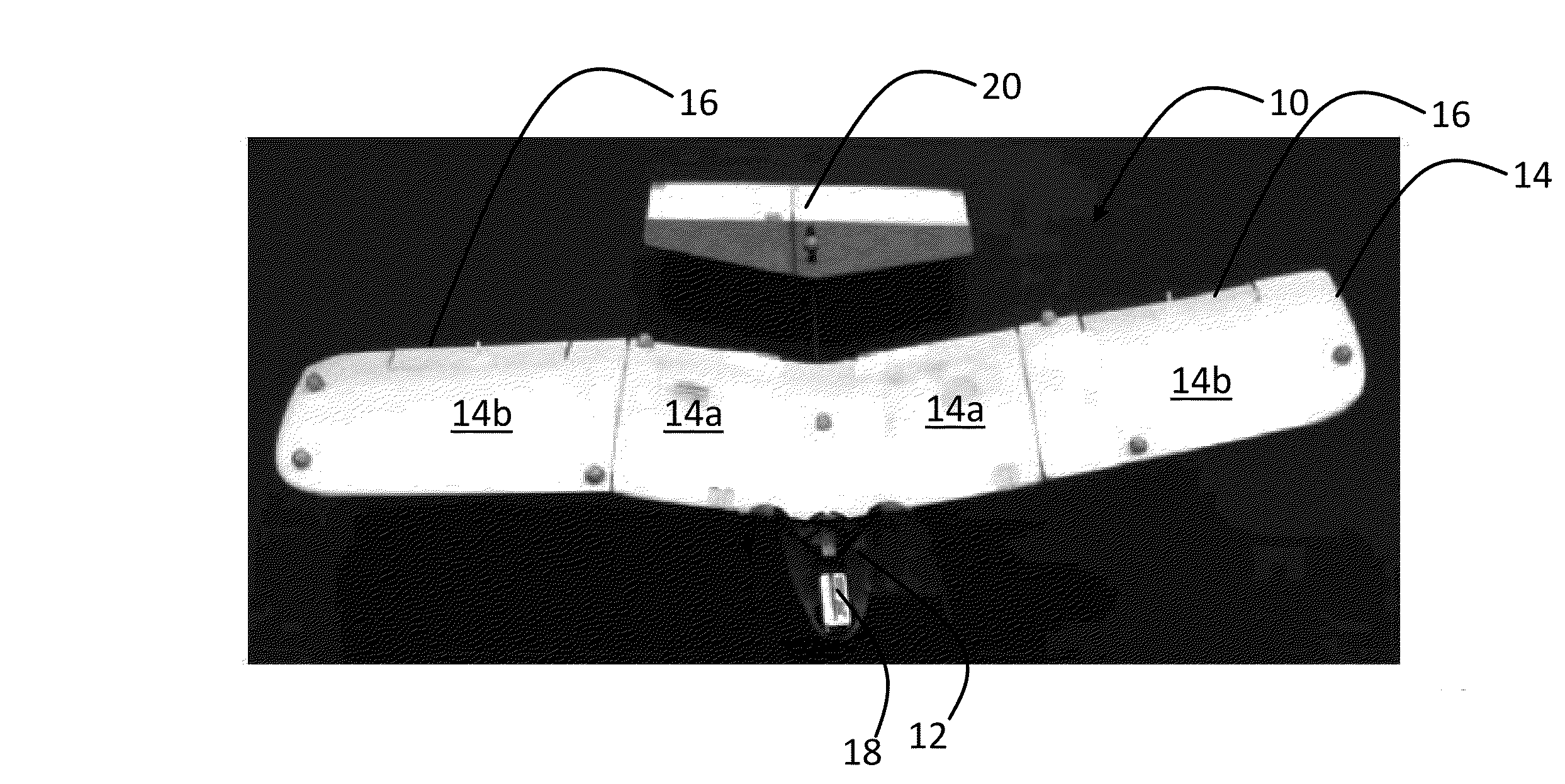
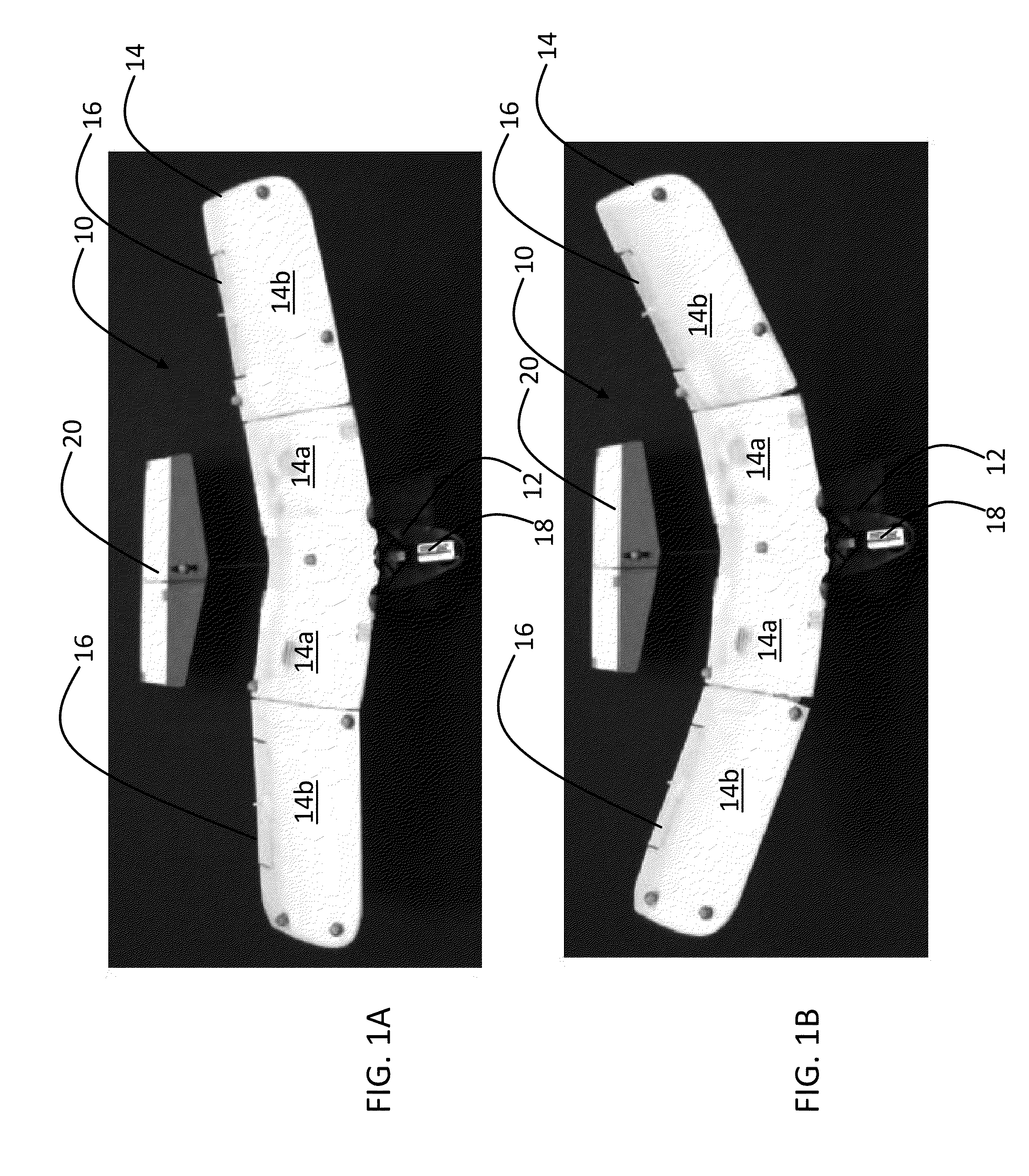
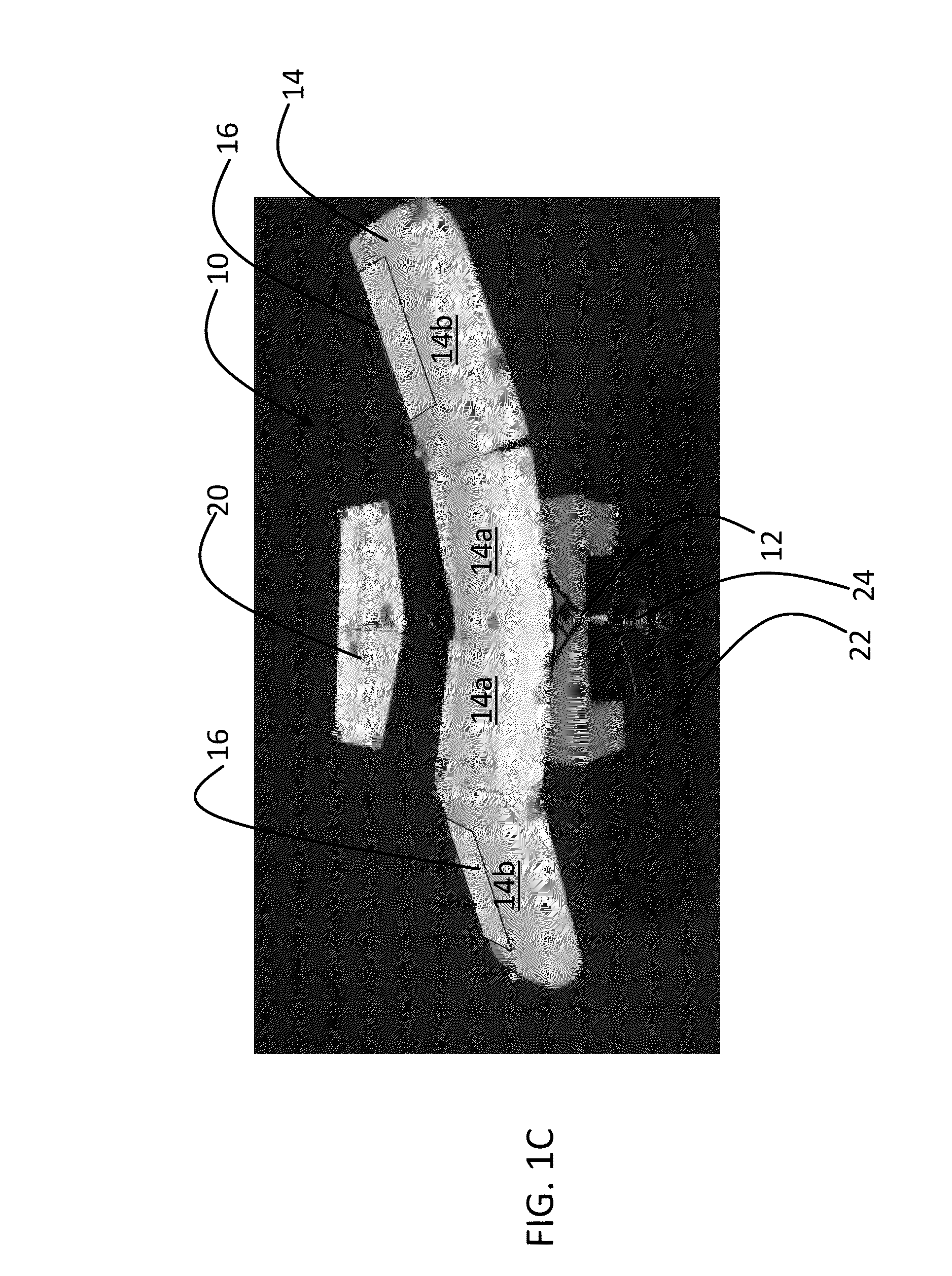
This invention is a small aerial vehicle that can glide in controlled ways. It has a flat bottom and a forward facing wing with flaps that can be controlled to change the angle at which it flies. This allows for effective control of the aircraft's speed and yaw (direction of flight). The vehicle does not have a tail or other stabilizers.

Problems solved by technology

An asymmetric wing setting naturally produces a yawing moment, however.
With a monolithic wing, this approach can impair turning because the side force from the deflected wing may adversely dominate the side force required for turn (in a right turn, the deflected winglet produces a leftward force, whereas a rightward force is required to sustain / aid the turn).
This can cause immense problems for yaw control, particularly when the angle of attack varies across the three regions in the course of a maneuver.
There was not a solution proposed for these problems in this paper.
This unresolved problem had to do with yaw control effectiveness changing its sign inside the routinely flown flight envelope.
Basically, every control law assumes that the sign of control effectiveness is known; if it changes sign inside the envelope and does so as a function of several variables, it is virtually impossible to design a robust, reliable controller.
Thus, this paper did not provide a practical solution for a tailless micro aerial aircraft.

Method used


Image

  • Controlled transitory or sustained gliding flight with dihedral angle and trailing flaps
  • Controlled transitory or sustained gliding flight with dihedral angle and trailing flaps
  • Controlled transitory or sustained gliding flight with dihedral angle and trailing flaps

Examples


Embodiment Construction

[0018]An embodiment of the invention is a vertical tailless micro aerial vehicle with a pair of articulated wings. The aircraft is controlled using wing articulation, together with trailing edge flaps, for effective yaw control across the flight envelope. The dihedral angles can be varied symmetrically on both wings to control the aircraft speed independently of the angle of attack and flight-path angle, while an asymmetric dihedral setting can be used to control yaw in the absence of a vertical tail. Actuators control the dihedral settings of each wing independently, and according to the mathematical formulation of closed loop control in the attachments, to achieve controlled sustained or transitory gliding flight. The wings are set ahead of the vehicle's center of gravity. Wing dihedral alone can be varied asymmetrically to perform rapid turns and regulate sideslip. The wings include trailing edge flaps. The trailing edge flaps are deflected downwards by a predetermined minimum am...


PUM


Abstract

A micro aerial vehicle capable of controlled transitory or sustained gliding flight. The vehicle includes a fuselage. A pair of articulated wings are forward of a center of gravity of the vehicle, the wings being articulated and having trailing edge flaps, and having actuators for controlling the dihedral angles of the wings and the flaps for effective yaw control across the flight envelope. The dihedral angles can be varied symmetrically on both wings to control the aircraft speed independently of the angle of attack and flight-path angle, while an asymmetric dihedral setting can be used to control yaw and the actuators control the dihedral settings of each wing independently. The aircraft lacks a vertical tail or other vertical stabilizer.

Description

PRIORITY CLAIM AND REFERENCE TO RELATED APPLICATION[0001]The application claims priority under 35 U.S.C. §119 from prior provisional application Ser. No. 61 / 726,663, which was filed Nov. 15, 2012, and which is incorporated by reference herein.STATEMENT OF GOVERNMENT INTEREST[0002]This invention was made with government support under contract number FA95500910089 awarded by the Air Force Office of Scientific Research. The government has certain rights in the invention.FIELD[0003]A field of the invention is flight and flying devices, and particularly articulated wing micro aerial vehicles. Example applications of the invention include bio-inspired flight devices.BACKGROUND[0004]The dihedral angle is the upward angle measured from horizontal of the wings or tailplane of an aircraft. If there are multiple sections of a wing having different angles from horizontal, then the wing can be referred to as polyhedral. Wing dihedral angle is known to play a role in lateral-directional stability...

Claims


Application Information

Patent Timeline
IPC IPC(8): B64C3/38B64C19/00B64C39/02
CPCB64C3/385B64C19/00B64C39/028G05D1/105B64C3/42Y02T50/10B64U10/80B64U10/50
Inventor PARANJAPE, ADITYA AVINASHCHUNG, SOON-JO
Owner THE BOARD OF TRUSTEES OF THE UNIV OF ILLINOIS
Learn More