Canisterized satellite dispenser

a dispenser and canister technology, applied in the field of satellites, can solve the problems of difficult analytical modeling and damage potential, and achieve the effect of simplifying the design of canisterized satellites

Active Publication Date: 2014-10-30
PLANETARY SYST CORP
View PDF1 Cites 68 Cited by
  • Summary
  • Abstract
  • Description
  • Claims
  • Application Information

AI Technical Summary

Benefits of technology

[0019]It would be advantageous to provide a canisterized satellite dispenser that overcomes one or more of the sub-optimal features of conventional canisterized satellite dispenser, such as P-Pod and ISIPOD. It would be advantageous to provide a canisterized satellite dispenser that has one or more of the following features: fewer than four guiderails, preloaded contact with the satellite, a rectangular profile in each dimension, a dispensing mechanism that does not use a coil spring, and an inner profile that allows further supporting contact with the canisterized satellite.
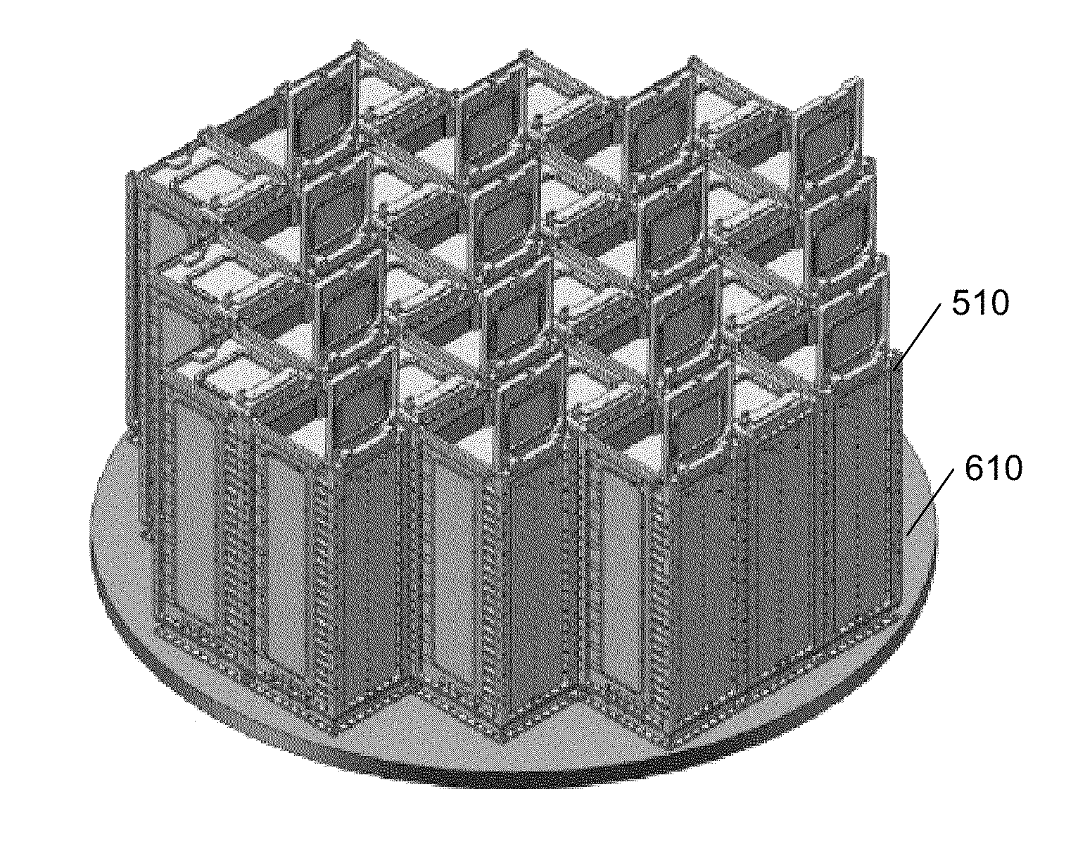
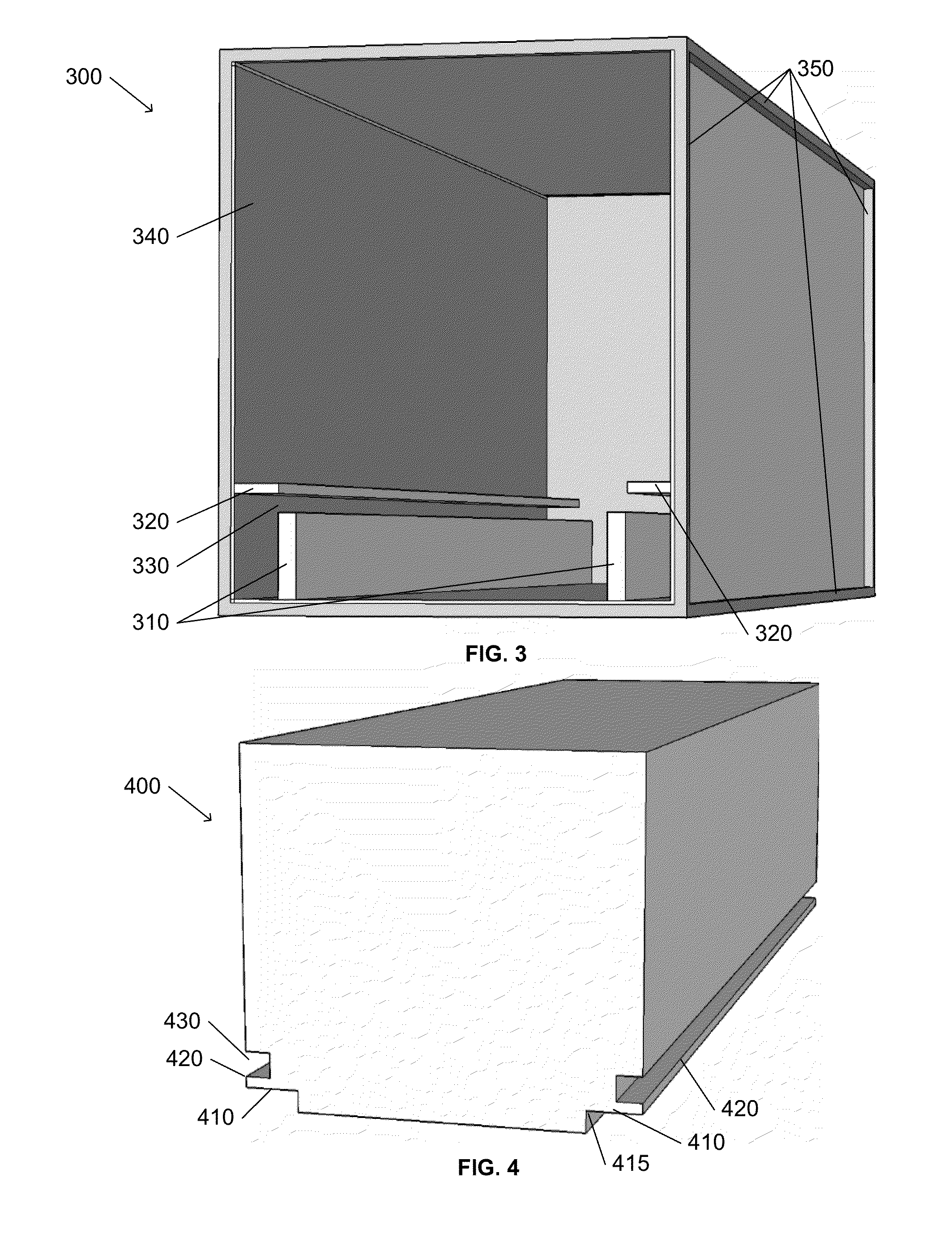
[0020]These advantages, and others, can be realized by a canisterized satellite dispenser that includes one or more of: a pair of guide channels that eliminate the requirement of a rectangular profile for the satellite; a preload system that secures the canisterized satellite during transport and launch, and releases to dispense the canisterized satellite; a constant-force spring to provide a uniform and predictable dispensing force; an external rectangular profile in each dimension; and internal support surfaces that simplify the design of canisterized satellites, particularly those with deployable components. Each canisterized satellite includes a pair of opposing flanges on a lower portion of the satellite that ride in a channel formed by the dispenser's guide rails and restraining flanges; no other support constraints are imposed. During travel and launch, the satellite flanges are held against the restraining flanges, rigidly fixing the satellite to the dispenser until the satellite is deployed.

Problems solved by technology

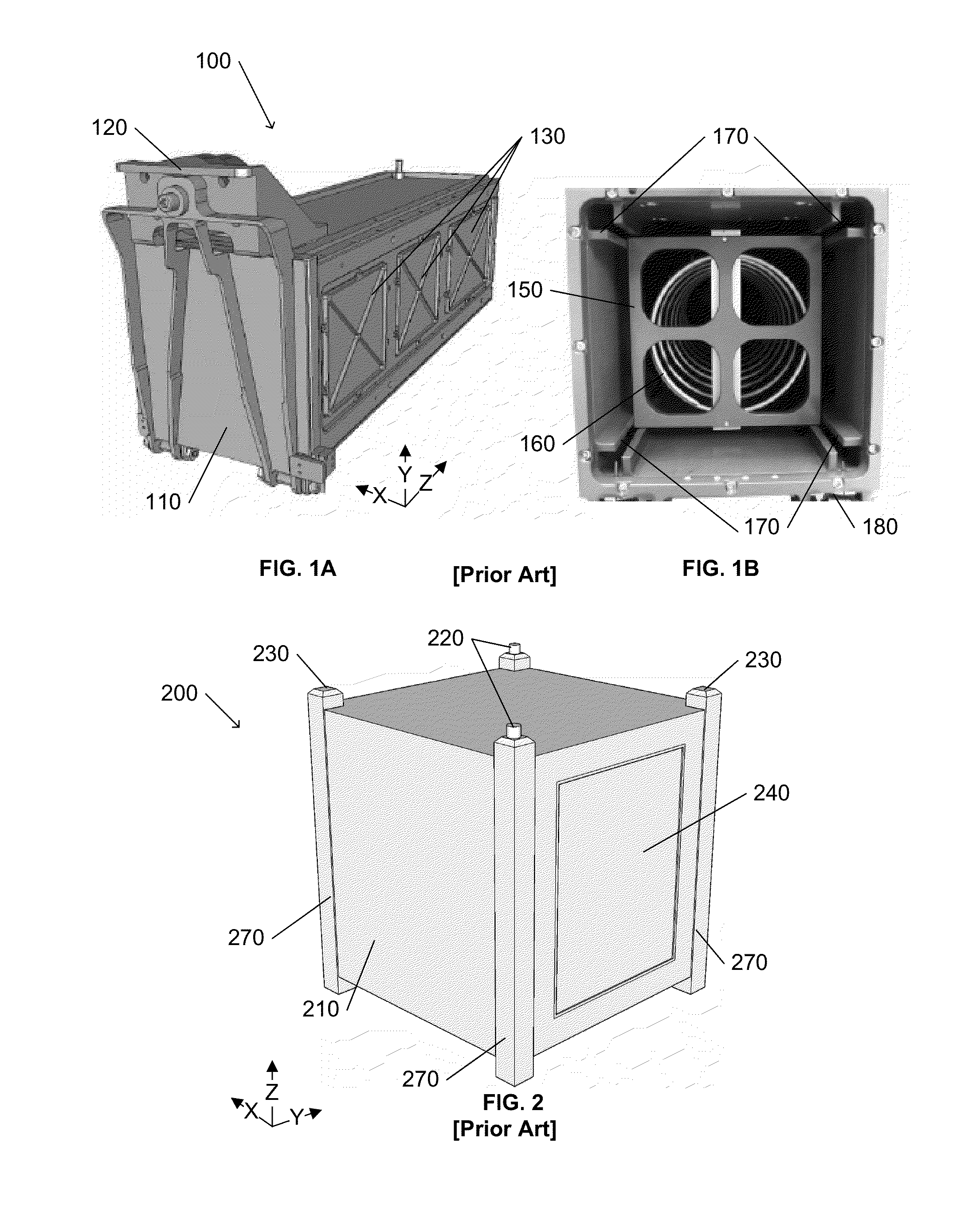
Although the gap may be slight (about 0.5 mm), it allows the CubeSat 200 to vibrate within the P-Pod 100 during transport and launch, which has damaging potential and is very difficult to analytically model.

Method used


Image

  • Canisterized satellite dispenser
  • Canisterized satellite dispenser
  • Canisterized satellite dispenser

Examples


Embodiment Construction

[0036]In the following description, for purposes of explanation rather than limitation, specific details are set forth such as the particular architecture, interfaces, techniques, etc., in order to provide a thorough understanding of the concepts of the invention. However, it will be apparent to those skilled in the art that the present invention may be practiced in other embodiments, which depart from these specific details. In like manner, the text of this description is directed to the example embodiments as illustrated in the Figures, and is not intended to limit the claimed invention beyond the limits expressly included in the claims. For purposes of simplicity and clarity, detailed descriptions of well-known devices, circuits, and methods are omitted so as not to obscure the description of the present invention with unnecessary detail.

[0037]The invention is presented using an example set of different sized satellite dispensers with features associated with this invention. One ...


PUM


Abstract

A canisterized satellite dispenser includes one or more of: a pair of guide rails that eliminate the requirement of a rectangular profile for the satellite; a preload system that secures the canisterized satellite during transport and launch, and releases to deploy the canisterized satellite; a constant-force spring to provide a uniform and predictable dispensing force; an external rectangular profile in each dimension; and internal support surfaces that simplify the design of canisterized satellites, particularly those with deployable components. Each canisterized satellite includes a pair of opposing flanges on a lower portion of the satellite that ride in a channel formed by the dispenser's guide rails and restraining flanges; no other support constraints are imposed. During travel and launch, the satellite flanges are held against the restraining flanges, rigidly fixing the satellite to the dispenser until the satellite is deployed.

Description

[0001]This application claims the benefit of U.S. Provisional Patent Application 61 / 815,867, filed 25 Apr. 2013.[0002]This invention was made with U.S. Government support under SBIR Contract No. FA9453-11-C-0016 awarded by the U.S. Air Force, titled “Canisterized Satellite Development for Operational Responsive Space”. The U.S. Government has certain rights in the invention.BACKGROUND AND SUMMARY OF THE INVENTION[0003]This invention relates to the field of satellites, and in particular to a dispenser for deploying canisterized satellites, such as CubeSat, from a larger spacecraft, such as a launch vehicle, a shuttle, or a space station.[0004]California Polytechnic State University (“Cal Poly”) initiated the CubeSat concept in 1999, to enable universities to perform space science and exploration. A basic CubeSat (“1U”) is a 10 cm1 cube (one liter in volume) having a mass of not more than 1.33 kg. Other common sizes are available, including a “2U” that is 20 cm×10 cm×10 cm, and a “3U”...

Claims


Application Information

Patent Timeline
Patent Type & Authority Applications(United States)
IPC IPC(8): B64G1/64
CPCB64G1/645B64G1/641B64G1/643
Inventor HOLEMANS, WALTERHEVNER, RYAN
Owner PLANETARY SYST CORP
Why Eureka
Try Eureka