Flow energy piezoelectric bimorph nozzle harvester

a piezoelectric bimorph and nozzle technology, applied in piezoelectric/electrostrictive/magnetostrictive devices, piezoelectric/electrostriction/magnetostriction machines, electrical equipment, etc., can solve the problems of reducing the life cycle of power generation devices, reducing the overall complexity and difficulty of bringing power down hol

Active Publication Date: 2014-10-30
CALIFORNIA INST OF TECH +1
View PDF2 Cites 29 Cited by
  • Summary
  • Abstract
  • Description
  • Claims
  • Application Information

AI Technical Summary

Benefits of technology

[0007]Aspects of the present invention relate generally to energy harvesting, and more specifically, to a flow energy harvesting apparatus integrated along a pipe or pipe sleeve or casing and utilizing a vibrating piezoelectric element or structure in such a way as to locally create energy produced from the flow for harvesting, for example, for use down hole in a deep well operation. Power can be produced locally using the flow energy harvesting device according to aspects of the present invention, thus eliminating the need to transmit power down hole to power sensors and actuators and, thus, reducing the overall complexity and difficulty of bringing power down hole.

Problems solved by technology

Operation of electronics, sensors, or actuators down hole in oil producing wells, or other deep well operations, is difficult, expensive, and generally requires power to be transmitted down hole in a production zone.
Transmitting generated power down hole is further complicated by difficulty in transmitting the power to flow past production packers.
While in the alternative, power may instead be generated down hole in lieu of being transmitted, with use of rotating turbo-machinery, this type of power generation device is subject to erosion or a short life-cycle.
Thus, the operating and replacement costs of existing down hole power generation devices make them difficult, complex, and expensive to operate and maintain.

Method used


Image

  • Flow energy piezoelectric bimorph nozzle harvester
  • Flow energy piezoelectric bimorph nozzle harvester
  • Flow energy piezoelectric bimorph nozzle harvester

Examples


Embodiment Construction

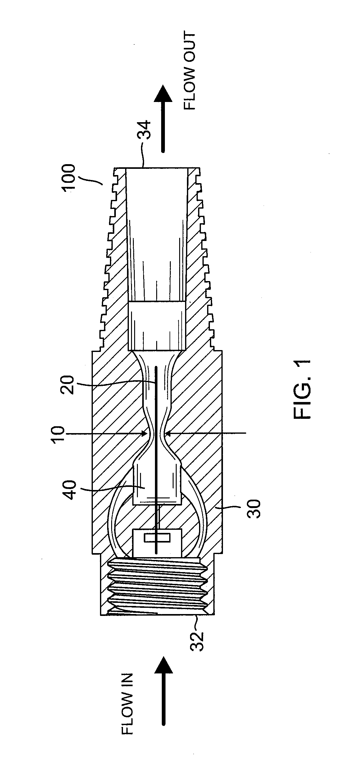
[0042]The detailed description set forth below in connection with the accompanying drawings is intended as a description of embodiments of a flow energy harvesting device, as provided in accordance with the present invention, and is not intended to represent the only forms in which the present invention may be constructed or utilized. The description sets forth the features of the present invention in connection with the illustrated embodiments. It is to be understood, however, that the same or equivalent functions and structures may be accomplished by different embodiments that are also intended to be encompassed within the spirit and scope of the invention. As denoted elsewhere herein, like reference numbers are intended to indicate like elements or features. Moreover, the sizes of the layers and regions in the drawings may be exaggerated for convenience of explanation.

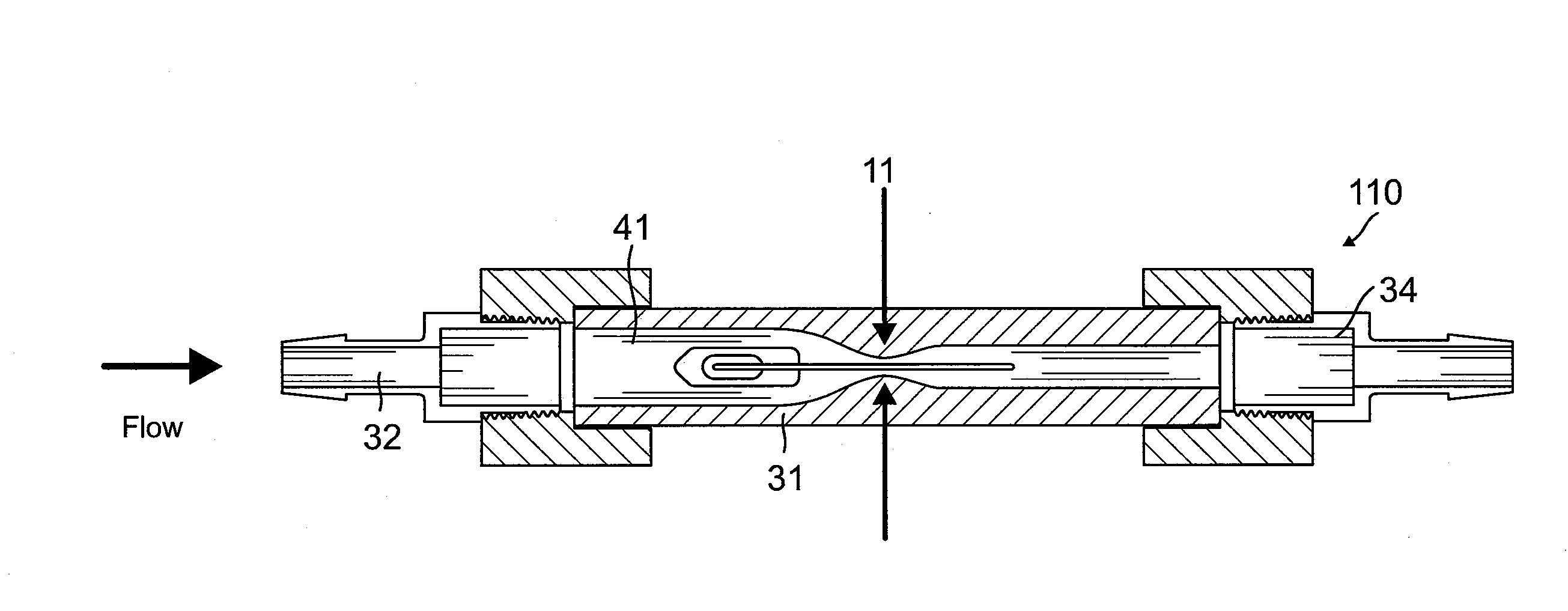
[0043]Embodiments of the present invention, as shown in FIG. 1, for example, are directed toward the use of nozzl...


PUM


Abstract

A flow energy harvesting device having a harvester pipe includes a flow inlet that receives flow from a primary pipe, a flow outlet that returns the flow into the primary pipe, and a flow diverter within the harvester pipe having an inlet section coupled to the flow inlet, a flow constriction section coupled to the inlet section and positioned at a midpoint of the harvester pipe and having a spline shape with a substantially reduced flow opening size at a constriction point along the spline shape, and an outlet section coupled to the constriction section. The harvester pipe may further include a piezoelectric structure extending from the inlet section through the constriction section and point such that the fluid flow past the constriction point results in oscillatory pressure amplitude inducing vibrations in the piezoelectric structure sufficient to cause a direct piezoelectric effect and to generate electrical power for harvesting.

Description

CROSS-REFERENCE TO RELATED APPLICATION[0001]This application claims priority to and the benefit of U.S. Provisional Application No. 61 / 815,647, filed with the U.S. Patent and Trademark Office on Apr. 24, 2013, the entire content of which is incorporated herein by reference.STATEMENT REGARDING FEDERALLY SPONSORED RESEARCH OR DEVELOPMENT[0002]The invention described herein was made in the performance of work under a National Aeronautics and Space Administration (NASA) contract, and is subject to the provisions of Public Law 96-517 (35 U.S.C. §202) in which the Contractor has elected to retain title.BACKGROUND[0003]1. Field[0004]Aspects of the present invention relate generally to energy harvesting, and more specifically, to a flow energy piezoelectric bimorph nozzle harvester.[0005]2. Description of the Related Art[0006]Operation of electronics, sensors, or actuators down hole in oil producing wells, or other deep well operations, is difficult, expensive, and generally requires power ...

Claims


Application Information

Patent Timeline
Patent Type & Authority Applications(United States)
IPC IPC(8): H02N2/18
CPCH02N2/185H10N30/306
Inventor SHERRIT, STEWARTWALKEMEYER, PHILLIP E.HALL, JEFFREY L.LEE, HYEONG JAECOLONIUS, TIMTOSI, LUIS PHILLIPEKIM, NAMHYOSUN, KAICORBETT, THOMAS GARYARRAZOLA, ALVARO JOSE
Owner CALIFORNIA INST OF TECH
Why Eureka
Try Eureka