Time-multiplexed broadband and multi-filtered electro-optic sensor

a multi-filtered electro-optic and broadband technology, applied in the field of electro-optic sensors, can solve the problems of inability to accurately detect the target at long ranges,

Active Publication Date: 2014-10-30
RAYTHEON CO
View PDF4 Cites 45 Cited by
  • Summary
  • Abstract
  • Description
  • Claims
  • Application Information

AI Technical Summary

Benefits of technology

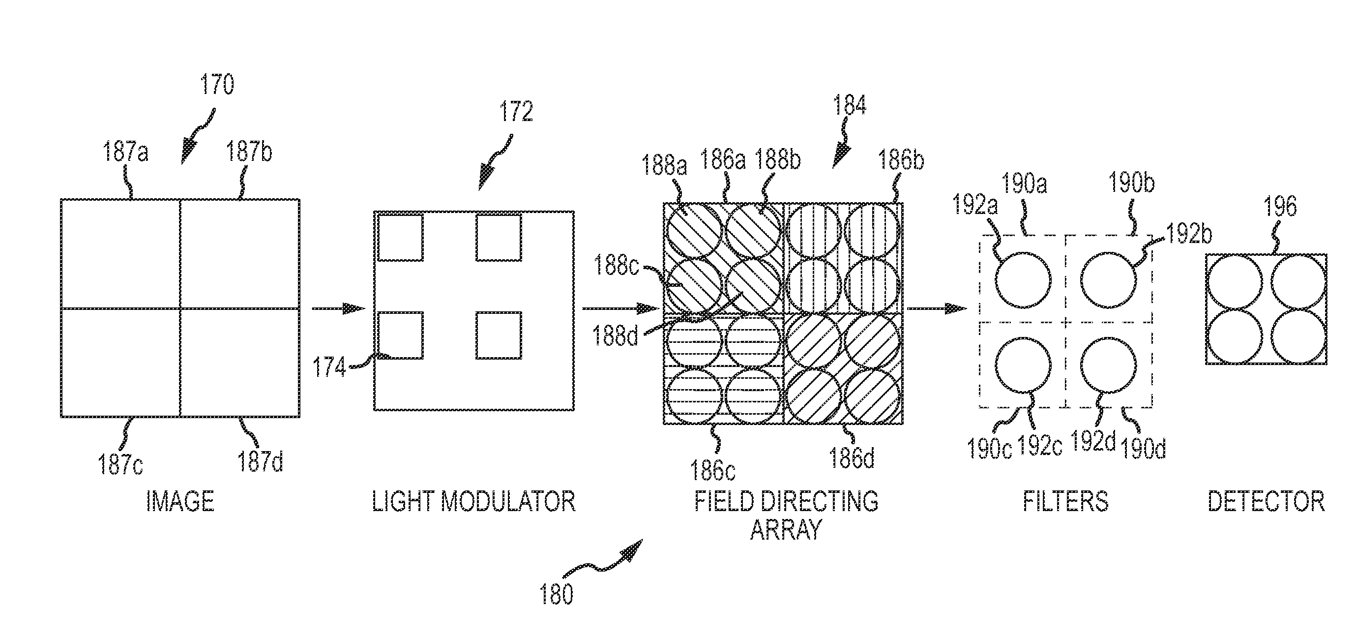
[0020]In another embodiment of the multi-filtered channel, a light modulator having addressable elements that can be mapped to individual optical tilt elements in the tilt cells may be configured to time de-multiplex different portions of the FOV that are spatially overlapped on the same detector pixel. The detector is configured to read out the electrical signals over an appropria

Problems solved by technology

However, due to its much higher spatial resolution, and detection of passive radiation, there are fewer incident photons per pixel, and the passive imaging mode may not have the sensitivity (i.e. S

Method used


Image

  • Time-multiplexed broadband and multi-filtered electro-optic sensor
  • Time-multiplexed broadband and multi-filtered electro-optic sensor
  • Time-multiplexed broadband and multi-filtered electro-optic sensor

Examples


case 1

[0064]Assume a 20×20 pixel detector that is divided into 4 10×10 sub-regions to detect 4 filtered sub-channels. Consider a field directing array having 100×φtilt cells with each cell including four optical tilt elements. A light modulator has 400×400 addressable elements. Each light modulator element is mapped to a single optical tilt element. 10×10 optical tilt elements, hence 10×10 portions of the FOV are mapped to and overlap each detector pixel. The light modulator is addressed to serial scan each addressable element, hence each optical tilt element in a 10×10 block to map a single portion of the FOV onto a given detector pixel during an integration period. By stitching the electrical signals together the 20×20 pixel detector can produce 100×100 pixel images for each of the four filtered sub-channels.

case 2

[0065]Assume a 20×20 pixel detector that is divided into 4 10×10 sub-regions to detect 4 filtered sub-channels. Consider a field directing array having 50×50 tilt cells with each cell including four optical tilt elements. A light modulator has 400×400 addressable elements such that 10×10 portions of the FOV are mapped to and overlap each detector pixel. A 2×2 block of addressable elements is mapped to each optical tilt element and in turn 5×5 blocks of tilt elements are mapped to and overlap each detector pixel. The light modulator is addressed to serial scan each addressable element in the 2×2 blocks mapped to each optical tilt element and the 5×5 blocks of optical tilt elements to map a single portion of the FOV onto a given detector pixel during an integration period. By stitching the electrical signals together the 20×20 pixel detector can produce 100×100 pixel images for each of the four filtered sub-channels.

[0066]Comparing Cases 1 and 2, the time required to scan the full fil...


PUM


Abstract

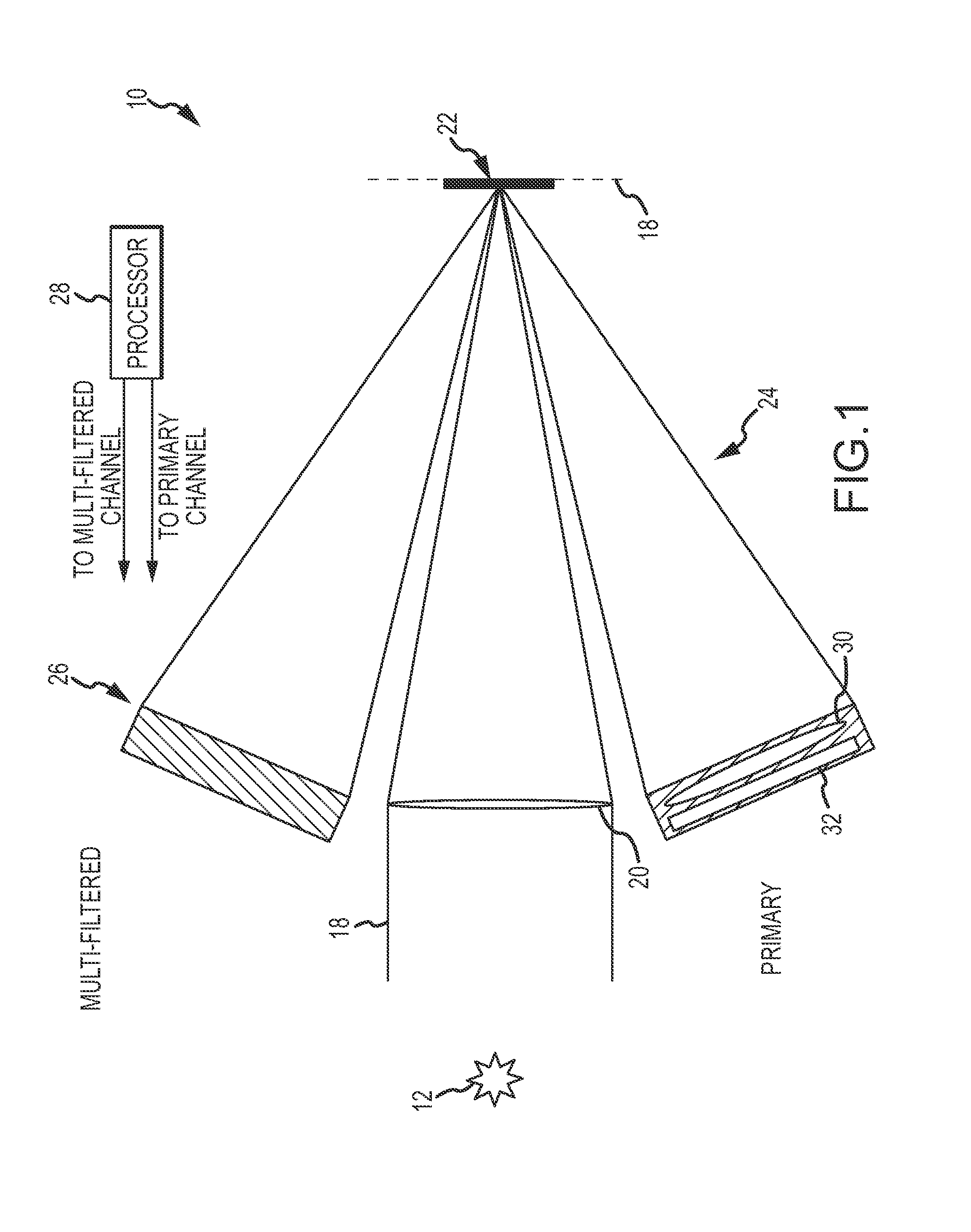
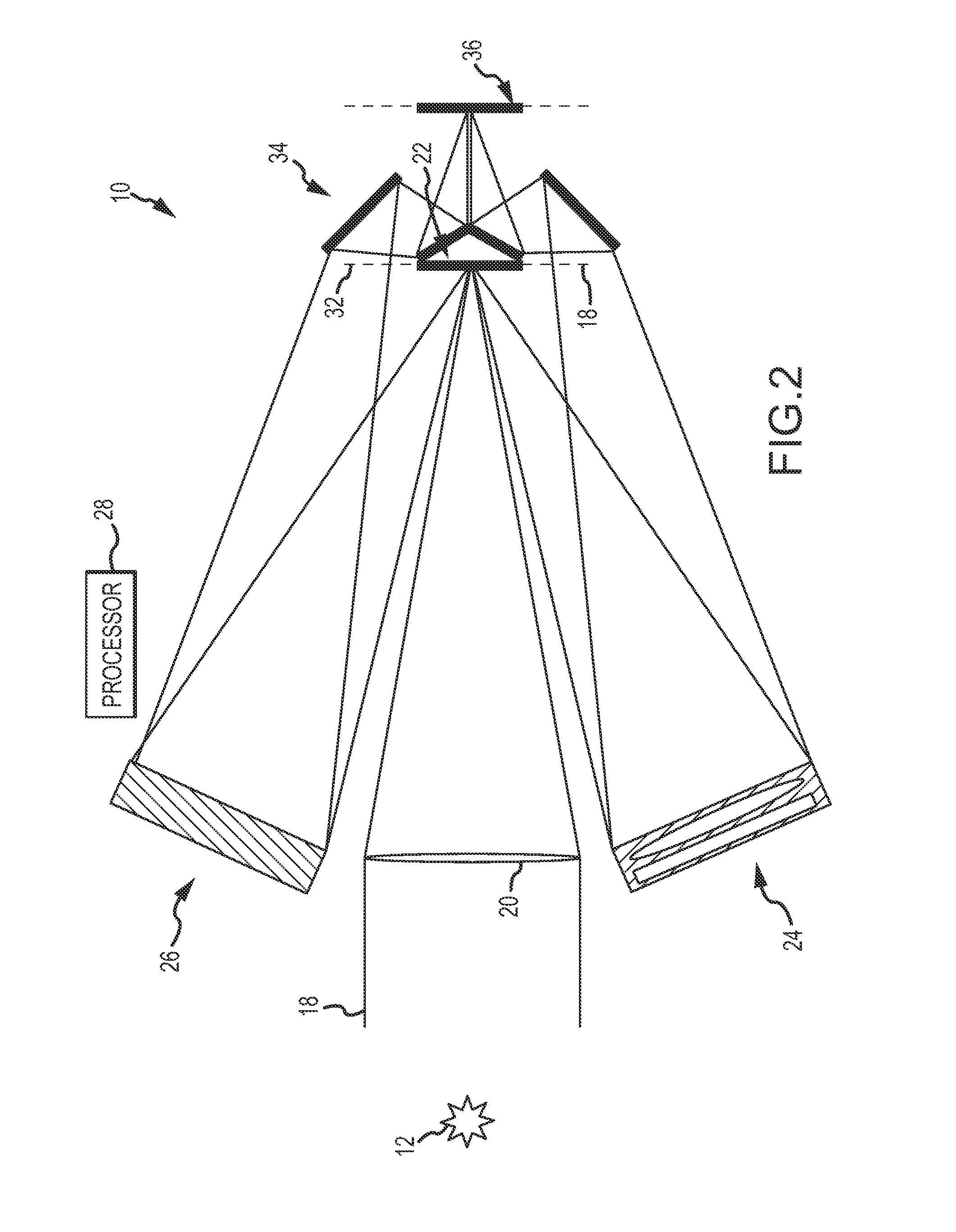
An EO sensor is configured to time multiplex a primary optical channel that provides high detection sensitivity to maintain high SNR and a multi-filtered optical channel that provides detection in different measurement bands (e.g. spectral, polarization, amplitude or phase). The channels may, for example, be time multiplexed based on range to target or within each integration period of the EO sensor. The multi-filtered optical channel uses a field directing array to sample the FOV to form different optical sub-channels that are filtered by different optical filters. These sub-channels may be spatially multiplexed onto different sub-regions of the detector or may be time multiplexed onto the entire detector. The light modulator used to time multiplex the primary and multi-filtered optical channels may be used to time de-multiplex spatially overlapping regions of the FOV onto a pixel of the detector in order to detect high spatial resolution images with low resolution detectors.

Description

BACKGROUND OF THE INVENTION[0001]1. Field of the Invention[0002]This invention relates to electro-optic (EO) sensors configured to detect both broadband and multi-filtered signatures. These EO sensors may be used in guided munitions and surveillance systems among other applications.[0003]2. Description of the Related Art[0004]Many guided munitions (e.g. self-propelled missiles, rockets, gun-launched projectiles or aerial bombs) use an EO sensor to detect and guide the munition to its target. The sensor's ability to detect and initiate target tracking at long standoff ranges to the target is critical. To accomplish this, the sensor must maintain a minimum signal-to-noise ratio (SNR) from the target signature.[0005]In a semi-active laser (SAL) mode, the sensor detects active guidance radiation in the form of laser radiation from a SAL designator that is reflected off of the target and locks onto the laser spot to provide line-of-sight (LOS) error estimates at an update rate required b...

Claims


Application Information

Patent Timeline
IPC IPC(8): G01S17/66
CPCG01S17/66F41G7/2253F41G7/2293G01S3/784G02B26/0875G02B26/10G02B27/1013F41G7/008
Inventor STREUBER, CASEY T.EASTON, MICHAEL P.PFLIBSEN, KENT P.
Owner RAYTHEON CO
Why Eureka
Try Eureka