Motor-driven compressor

Inactive Publication Date: 2014-10-30
TOYOTA IND CORP
View PDF0 Cites 2 Cited by
  • Summary
  • Abstract
  • Description
  • Claims
  • Application Information

AI Technical Summary

Benefits of technology

The present invention is a motor-driven compressor that includes an electric driving mechanism, a compression mechanism, and a motor drive circuit for driving the electric driving mechanism. The electric driving mechanism has a stator, a rotor, a drive shaft, a lead wire, and a cluster block. The housing has a main body portion, a bulging portion, and a partition wall which separates the stator accommodation chamber and the cluster block accommodation chamber. The technical effects of the invention include efficient compression, improved cooling efficiency, and simplified structure.

Problems solved by technology

Therefore, in the compressor, stress that acts on the outer circumferential surface of the stator core becomes ununiform when the stator core is shrinkage-fitted into the stator accommodation chamber of the housing, and circularity of the stator core after being fixed tends to be low.
Therefore, in this compressor, the electric driving mechanism hardly keeps high efficiency.

Method used


Image

  • Motor-driven compressor
  • Motor-driven compressor
  • Motor-driven compressor

Examples


embodiment 1

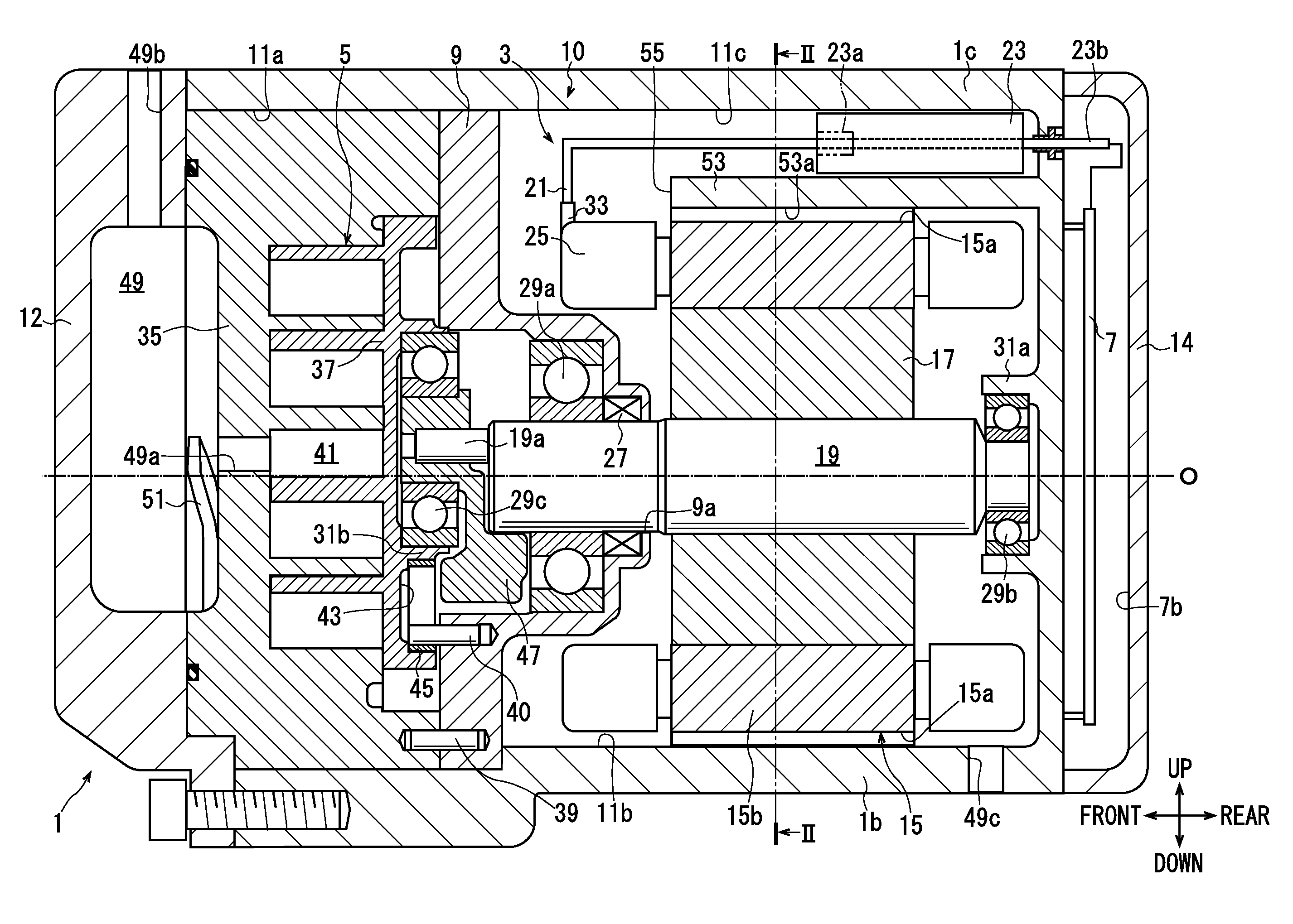
[0016]A compressor of embodiment 1 is used in an air-conditioning apparatus that is mounted on a hybrid vehicle and performs temperature control of a vehicle interior. As shown in FIG. 1, the compressor includes a housing 1, an electric driving mechanism 3, a compression mechanism 5 and a motor drive circuit 7.

[0017]The housing 1 is formed of a main housing 10, an end housing 12 and a cover 14. The main housing 10 is in a bottomed cylindrical shape. The end housing 12 is located at a front of the main housing 10 to close an opening of the main housing 10. The cover 14 is fixed to a rear end of the main housing 10.

[0018]In the main housing 10, a fixed block 9 is supported. A front portion of the housing 1 is configured by a front portion of the main housing 10 that is located forward of the fixed block 9, and the end housing 12. In the front portion, a compression mechanism accommodation chamber 11a is formed. In the compression mechanism accommodation chamber 11a, the compression me...

embodiment 2

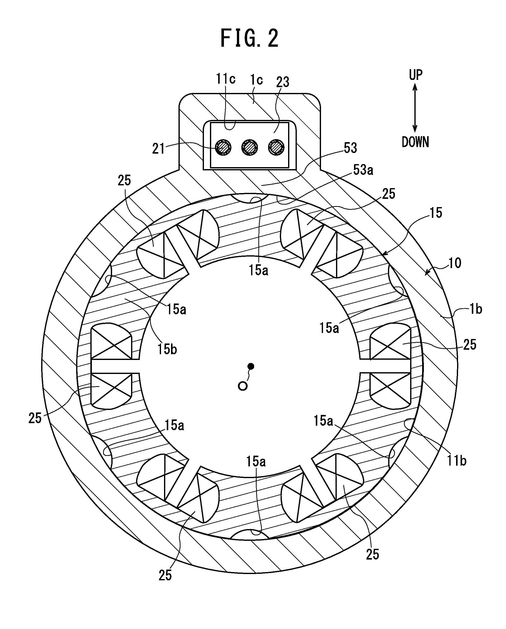
[0037]As shown in FIG. 3, in a compressor of embodiment 2, a slit 57 that extends in an axial direction is formed in a partition wall 54. The slit 57 allows the stator accommodation chamber 11b and the cluster block accommodation chamber 11c to communicate with each other.

[0038]Further, the cluster block 23 is fixed to the stator core 15b via a fitting member 59 of a resin. The fitting member 59 is located in the slit 57.

[0039]Further, in this compressor, a plurality of refrigerant channels 61 are formed in the inner circumferential surface of the main body portion 1b. The slit 57 and the respective refrigerant channels 61 are spaced equiangularly from one another in a circumferential direction of the main body portion 1b. Further, the slit 57 and the respective refrigerant channels 61 are formed to have widths equal to one another in the circumferential direction of the main body portion 1b. The other configuration is similar to that of embodiment 1.

[0040]In this compressor, by ins...


PUM


Abstract

A motor-driven compressor in which an electric driving mechanism is capable of keeping high efficiency. The compressor includes an electric driving mechanism, a compression mechanism and a motor drive circuit. The electric driving mechanism is accommodated in a housing. The housing has a main body portion in a cylindrical shape, a bulging portion that bulges in a radially outward direction from the main body portion, and a partition wall. In the main body portion, a stator accommodation chamber is formed. In the stator accommodation chamber, a stator of the electric driving mechanism is accommodated. In the bulging portion, a cluster block accommodation chamber is formed. In the cluster block accommodation chamber, a cluster block is accommodated. A partition wall separates the stator accommodation chamber and the cluster block accommodation chamber in a radial direction. The main body portion and the partition wall support a stator core.

Description

TECHNICAL FIELD[0001]The present invention relates to a motor-driven compressor.BACKGROUND ART[0002]Japanese Patent Laid-Open No. 2010-59809 discloses a conventional motor-driven compressor (hereinafter, simply called a compressor). The compressor includes an electric driving mechanism, a compression mechanism that is driven by the electric driving mechanism and performs compression of a refrigerant, and a motor drive circuit for driving the electric driving mechanism.[0003]The electric driving mechanism is accommodated in a housing. The electric driving mechanism has a stator, a rotor, a drive shaft, a lead wire and a cluster block. The stator has a stator core and a coil provided at the stator core. The rotor is rotatably provided in the stator. The drive shaft is fixed to the rotor. The drive shaft drives the compression mechanism. The lead wire is connected to the coil. The cluster block electrically connects the lead wire to the motor drive circuit.[0004]The housing has a main ...

Claims


Application Information

Patent Timeline
IPC IPC(8): F04C29/00F04C18/02
CPCF04C18/0215F04C29/0085F04C23/008F04C2240/803F04C2240/808
Inventor INAGAKI, TOMOYOSHIADANIYA, TAKUNAGANO, HIROKINARUSE, TAKUYA
Owner TOYOTA IND CORP
Why Eureka
Try Eureka