
Method to control a hybrid drive train

Inactive Publication Date: 2009-12-17
ZF FRIEDRICHSHAFEN AG
View PDF26 Cites 108 Cited by
  • Summary
  • Abstract
  • Description
  • Claims
  • Application Information

AI Technical Summary

Benefits of technology

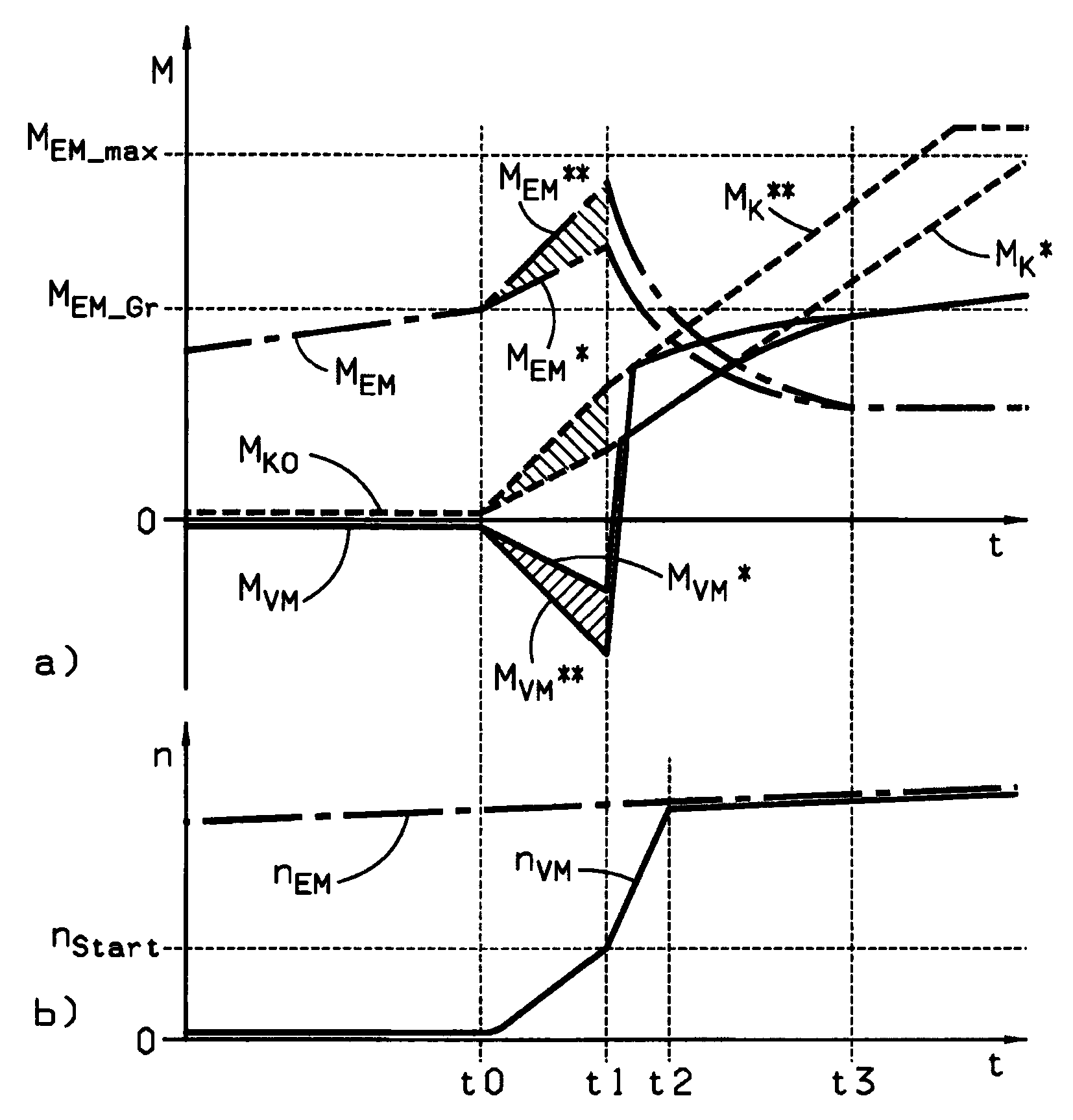
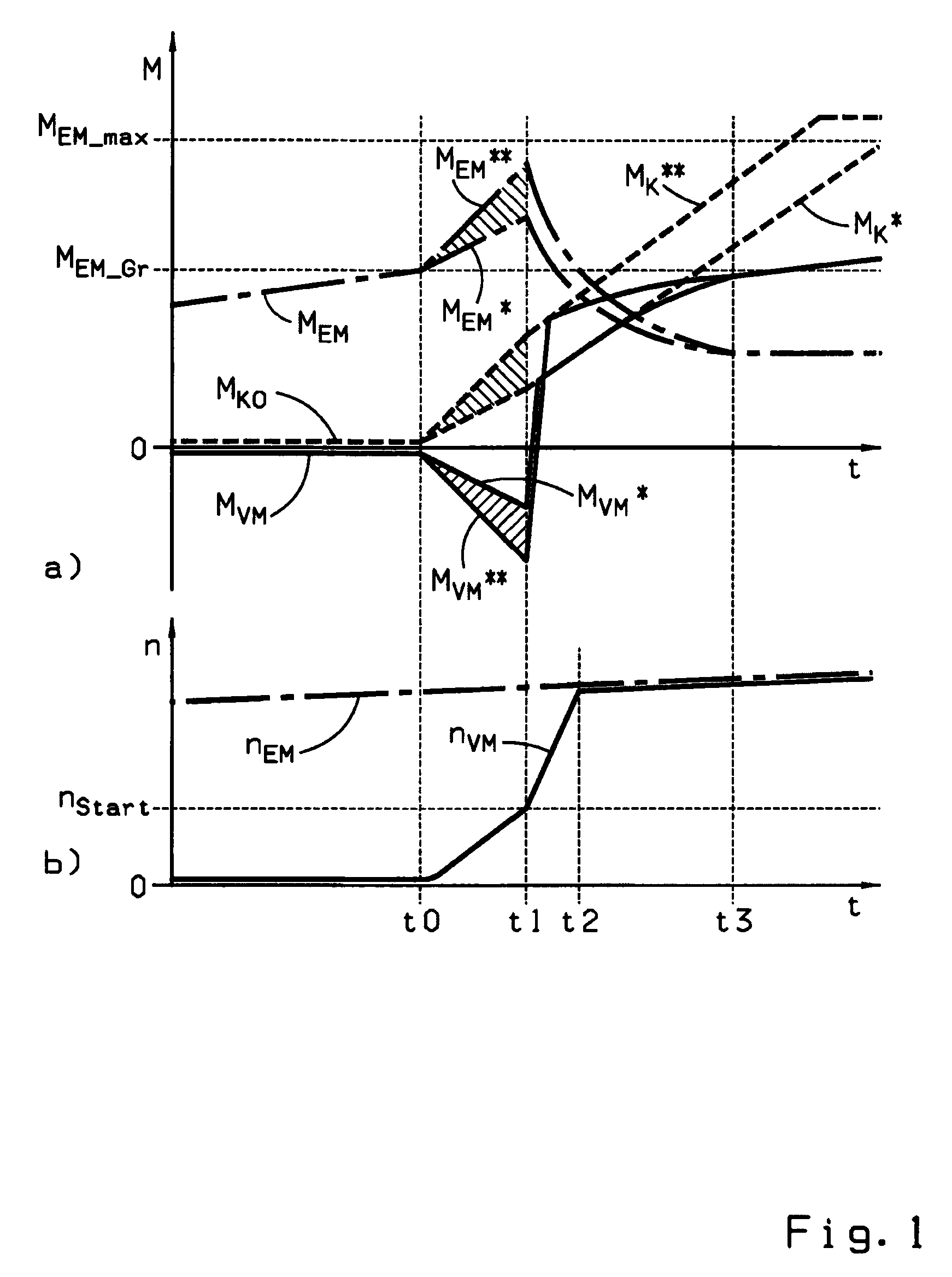
[0019]Accordingly, the method of the invention proceeds from a hybrid drive train of a motor vehicle which is designed as a parallel hybrid drive with a serial arrangement of the internal combustion engine, a clutch, an electric motor operating as an engine and generator, and a drive transmission having an output drive connected to the axle input drive of the motor vehicle. When the motor vehicle is in traction mode, a change should occur from an electric drive mode into a combination drive mode or into an internal combustion mode in a generally smooth and thus comfortable and low-wear manner. The electric drive mode is characterized in that the internal combustion engine is shut off, the clutch is disengaged and the electric motor is being operated as an engine. In the combination drive mode, the internal combustion engine is in traction mode, the clutch is engaged and the electric motor is being operated as an engine. In the internal combustion drive mode, the internal combustion engine is in traction operation, the clutch is engaged and the electric motor is disconnected.
[0021]In order to implement the change from the electric drive mode into the combination drive mode or into the internal combustion drive mode independently of the current operating parameters of the internal combustion engine and in an essentially reproducible manner, the invention provides that engaging the clutch is regulated at least until a starting rotational speed nStart of the internal combustion engine is reached, so that an acceleration dnVM / dt of the internal combustion engine is adjusted which corresponds to a predetermined progression of rotational speed nVM(t). In order to thus avoid a drop of torque on the input shaft of the drive transmission and to achieve essentially steady torque progression during this action, the torque MEM of the electric motor is increased by the amount that the transmissible torque MK on the clutch is increased by the engagement process (dMEM / dt=dMK / dt, ΔMEM=ΔMK). Accordingly, in this phase the transferable torque MK forms the control value which is tracked by the torque MEM produced by the electric motor.
[0022]As a result of the fact that the internal combustion engine is always accelerated and started in the same amount of time independent of the current operating parameters which, like the engine temperature TVM and the current state of maintenance and repair of the internal combustion engine, basically influence the breakaway torque for cranking of the internal combustion engine and the drag torque for subsequent acceleration of the internal combustion engine up to the starting rotational velocity nStart, the corresponding changes of the hybrid drive mode always occur essentially in the same way. This simplifies the control of additional functions of the hybrid drive train and provides passengers within the vehicle with an improved sensation of comfort.
[0043]Now if a gear shift is intended in the time proximity to the change of the hybrid driving mode, then this gear shift process should be carried out simultaneously with the change to the hybrid driving mode, since the torque peaks caused by the shift and the torque peaks caused by the change to hybrid drive mode can be partly eliminated or at least will be perceived by vehicle passengers as a single, comfort-reducing load jolt.

Problems solved by technology

In addition, the known control methods are often restricted to the solving of partial problems occurring in the control of the particular hybrid drive train.
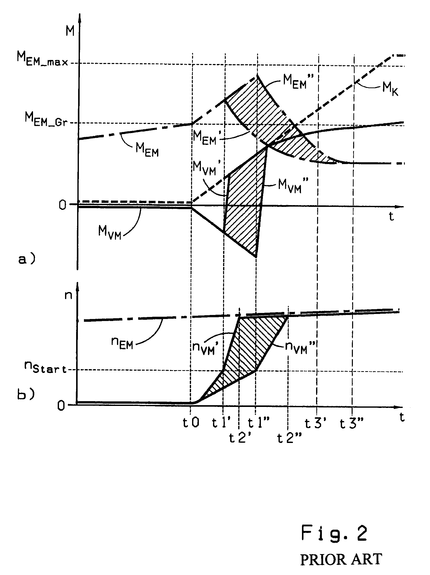
Starting of the internal combustion engine by engaging the clutch located between engine and the electric motor, however, is problematic, since the breakaway torque for cranking of the internal combustion engine and the drag torque (which must be subsequently overcome to accelerate the internal combustion engine up to the rotational speed which allows start-up of the internal combustion engine) are essentially dependent on operating parameters of the internal combustion engine, such as the engine temperature (coolant temperature and oil temperature) and on the maintenance and wear state of the internal combustion engine.

Method used


Image

  • Method to control a hybrid drive train
  • Method to control a hybrid drive train
  • Method to control a hybrid drive train

Examples


Embodiment Construction

[0047]In the two diagrams of FIGS. 1 and 2 two different processes are illustrated, based on relevant torque- and rotational speed profiles, which each relate to a hybrid drive train of a motor vehicle that is designed as a parallel hybrid with a serial arrangement of an internal combustion engine VM, a clutch K, an electric motor EM operable as an engine and a generator, and a drive transmission having a drive connection on the output side to a drive axle of the motor vehicle.

[0048]Based on the torque profiles of the internal combustion engine, of the electric motor and of the transmissible torque to the clutch, MVM(t), MEM(t), MK(t), illustrated in part a), and also based on the profiles of rotational speed nVM(t), nEM(t) of the internal combustion engine and of the electric motor illustrated in part b) of the figures, it is clear how in the traction mode of the motor vehicle a change from an electric drive mode, in which the internal combustion engine is shut off, the clutch is d...


PUM


Abstract

A method of controlling a hybrid drive train of a vehicle having, in series, an internal combustion engine, a clutch, an electric motor and a transmission with an output connected to the drive axle. During traction operation, the vehicle changes from an electric driving mode into a combination driving mode or a combustion engine driving mode, in that the clutch is engaged and the combustion engine torque is temporarily increased. The method includes regulating engagement of the clutch at least until reaching a starting rotational speed of the combustion engine such that the acceleration of the combustion engine occurs according to a predetermined progression of rotational speed and that the torque of the combustion engine is increased by the same amount as the transferable torque of the clutch is increased by the engagement process.

Description

[0001]This application claims priority from German patent application serial no. 10 2008 002 383.3 filed Jun. 12, 2008.FIELD OF THE INVENTION[0002]The invention relates to a method of controlling a hybrid drive train of a motor vehicle which is designed with serial arrangement of the internal combustion engine, a clutch, an electric motor operating as engine and generator, and a drive transmission having an output drive connection to the drive axle of the motor vehicle, wherein during thrust operation of the motor vehicle a change occurs from an electric driving mode with the internal combustion engine shut off, the clutch disengaged and an electric motor in engine operation into a combination driving mode with an internal combustion engine in thrust operation, the clutch engaged and an electric motor in engine operation, or into an internal combustion driving mode with an internal combustion engine in thrust mode, the clutch engaged and an electric motor shifted to a disconnected s...

Claims


Application Information

Patent Timeline
IPC IPC(8): B60W20/00B60W10/02G06F19/00B60W10/04B60K6/46
CPCB60K6/48Y10T477/26B60L2240/441B60L2240/445B60W10/02B60W10/06B60W10/08B60W20/00B60W2510/0275B60W2510/0638B60W2510/0676B60W2710/0661B60W2710/0666B60W2710/083Y02T10/6221Y02T10/6286Y02T10/642Y02T10/48B60L2240/423Y02T10/40Y02T10/62Y02T10/64B60K2006/268B60W20/40
Inventor ALLGAIER, BERNDTENBROCK, FRIEDRICHLEMP, THOMASGROMUS, MICHAEL
Owner ZF FRIEDRICHSHAFEN AG
Learn More