Multi-component non-biodegradable implant, a method of making and a method of implantation
a biodegradable, multi-component technology, applied in the field of multi-component implants, can solve the problems of limited healing ability, inability to heal, and inability to adapt to the needs of patients, and achieve the effects of facilitating integration, high or low viscosity, and maximizing integration
- Summary
- Abstract
- Description
- Claims
- Application Information
AI Technical Summary
Benefits of technology
Problems solved by technology
Method used
Image
Examples
example 1
Manufacture of the Hydrogel Portion of the Implant
[0191]All handling and fabrication techniques were performed aseptically to minimize contamination with bacteria and other infectious agents.
[0192]A collagen sponge (Ethicon Surgifoam, Ref #: 1974) was soaked in deionized water overnight until the entire sponge was saturated with water via capillary action. The sponges were transferred to 50 mL conical tubes and repeatedly centrifuged at 3000 g for 1 hour at a time, with gentle agitation of the tube between centrifugations to restore its original shape, until all remaining air bubbles had been removed.
[0193]The sponge was then impregnated through increasing gradients of liquid polyvinyl alcohol (PVA) from 1% to 5%, up to the desired final concentration of 10% PVA. The impregnated collagen sponge was then subjected to one freeze / thaw cycle (20 hours at −20° C. / 4 hours at 25° C.).
[0194]Next the frozen impregnated sponge was cored using a cutting die, and the center of each core was rem...
example 2
Manufacture of the Porous Rigid Base Portion of the Implant
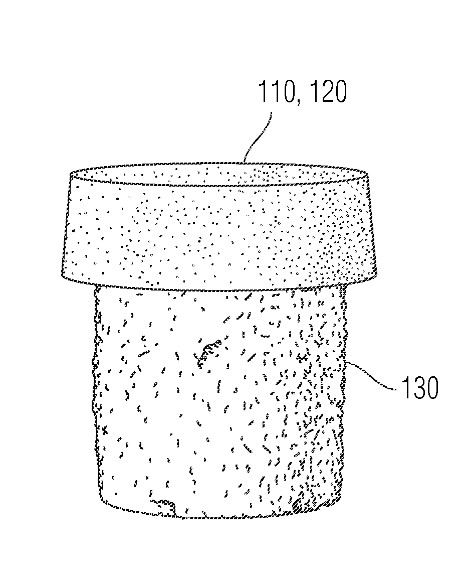
[0196]A titanium (Ti6A14V or Ti6A14VELI) cylinder with a diameter of 9 mm and pores of about 150 to 500 μm in size and a 3.8% taper at the bottom, was drilled with one additional hole (1.3 mm diameter and 4.5 mm deep) at the top surface of the base. A 0.5 mm step was also created. These bases were designed using computer aided design and created using techniques such as electron beam melting or by laser metal sintering.
example 3
Assembly of the Implant
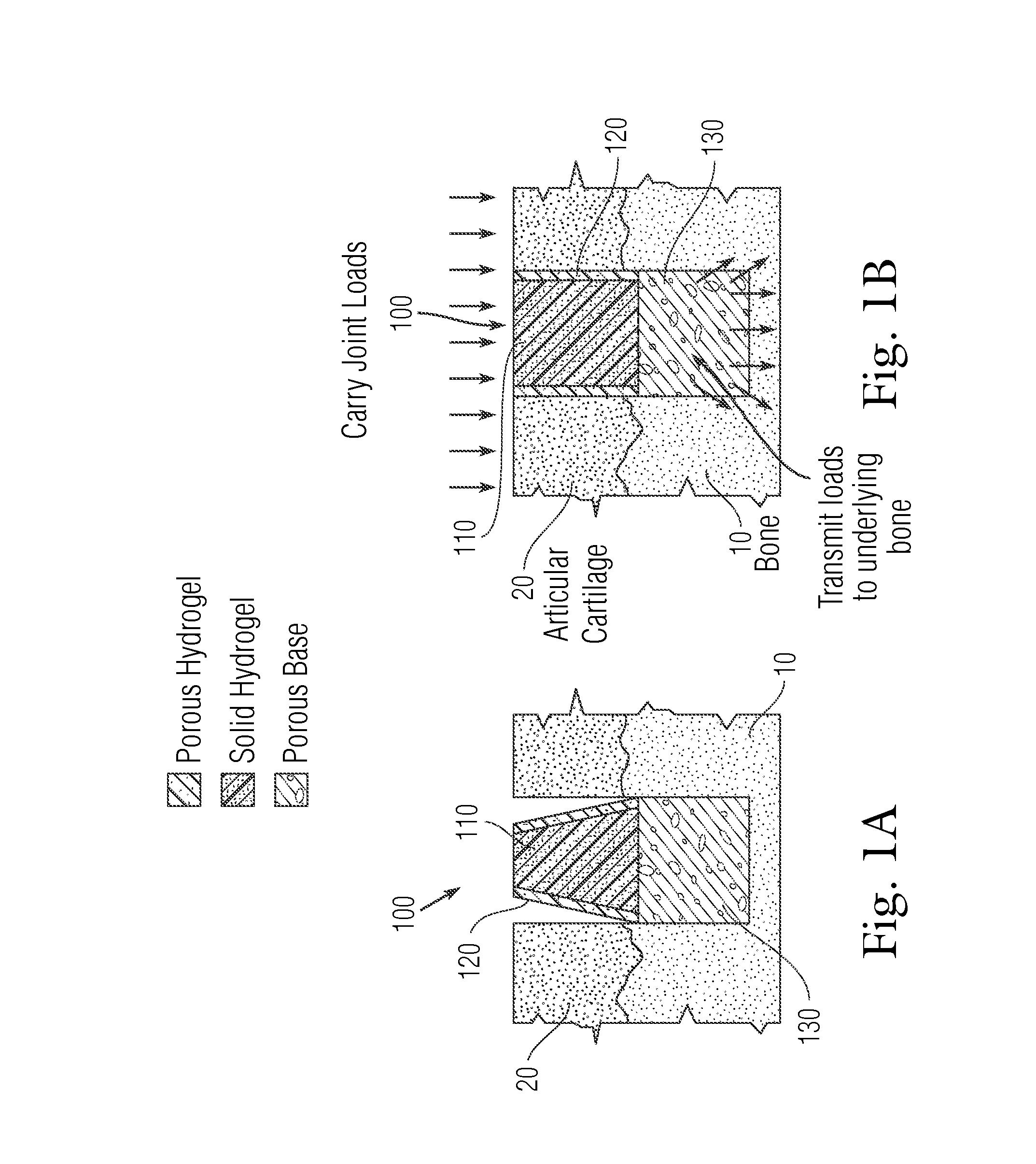
[0197]As illustrated in FIG. 11, the macropores in the porous metal base from Example 2 were filled with a low viscosity PVA solution (10% or 1.33 molar PVA in deionized water), and a volume of 50 μL of 20% (or 2.67 molar) PVA was injected across the entire surface of the porous metal using a syringe. Positive pressure was applied using a known weight of 500 grams over 30 seconds to drive a 20% liquid PVA solution into the pores of the porous rigid base. The weight was removed and the solid-porous hydrogel from Example 1 was placed onto the top surface of the porous metal. The assembled implant was then subjected to 3 freeze / thaw cycles (−20° C. for 20 hours / 40° C. for 4 hours) to crosslink the hydrogel portion and the liquid polymer interface. The collagen sponge in the porous periphery was removed by digestion using bacterial collagenase (Collagenase Type 2, Worthington Biochemical Corporation) for 16 hours to create the interconnected porous hydrogel struct...
PUM
| Property | Measurement | Unit |
|---|---|---|
| Temperature | aaaaa | aaaaa |
| Temperature | aaaaa | aaaaa |
| Fraction | aaaaa | aaaaa |
Abstract
Description
Claims
Application Information
 - R&D
- Intellectual Property
- Life Sciences
- Materials
- Tech Scout
- Unparalleled Data Quality
- Higher Quality Content
- 60% Fewer Hallucinations
Browse by: Latest US Patents, China's latest patents, Technical Efficacy Thesaurus, Application Domain, Technology Topic, Popular Technical Reports.
© 2025 PatSnap. All rights reserved.Legal|Privacy policy|Modern Slavery Act Transparency Statement|Sitemap|About US| Contact US: help@patsnap.com


