Wireless energy transfer

a technology of energy transfer and wires, applied in the direction of transmission, circuit arrangement, inductance, etc., can solve the problems of difficult integration or deployment of wireless energy transfer in many environments, deployment for many applications, etc., and achieve the effect of increasing increasing the temperature, and decreasing the capacitance of the heat sensitive elemen

Inactive Publication Date: 2014-11-06
WITRICITY CORP
View PDF8 Cites 285 Cited by
  • Summary
  • Abstract
  • Description
  • Claims
  • Application Information

AI Technical Summary

Benefits of technology

[0015]The insoles can include a heat sensitive element that is configured to detune the resonator from a set resonant frequency as a temperature of the heating element increases. The heat sensitive element can include a capacitive element coupled to the resonator coil,

Problems solved by technology

Wireless energy transfer may be difficult to incorporate or deploy in many environments.
Efficiency of ene

Method used


Image

  • Wireless energy transfer
  • Wireless energy transfer
  • Wireless energy transfer

Examples


Embodiment Construction

[0044]Wireless energy transfer can be configured for footwear applications. Energy may be wirelessly transferred to device resonators that may be attached to footwear, inside footwear, or associated with footwear. Transferred energy may be used to provide heating or cooling to the footwear, provide power or energy for sensors, electronics, or systems of the footwear.

[0045]Wireless energy stations may be used to transfer energy to footwear. Wireless energy stations may be configured as “warming stations” providing energy for heating in cold climates. Warming stations may be deployed in public transit locations, outdoors, ski areas, residences, and in other applications.

[0046]Wireless energy transfer may be used in hearing aids, underwater submersibles, clothing, and other applications.

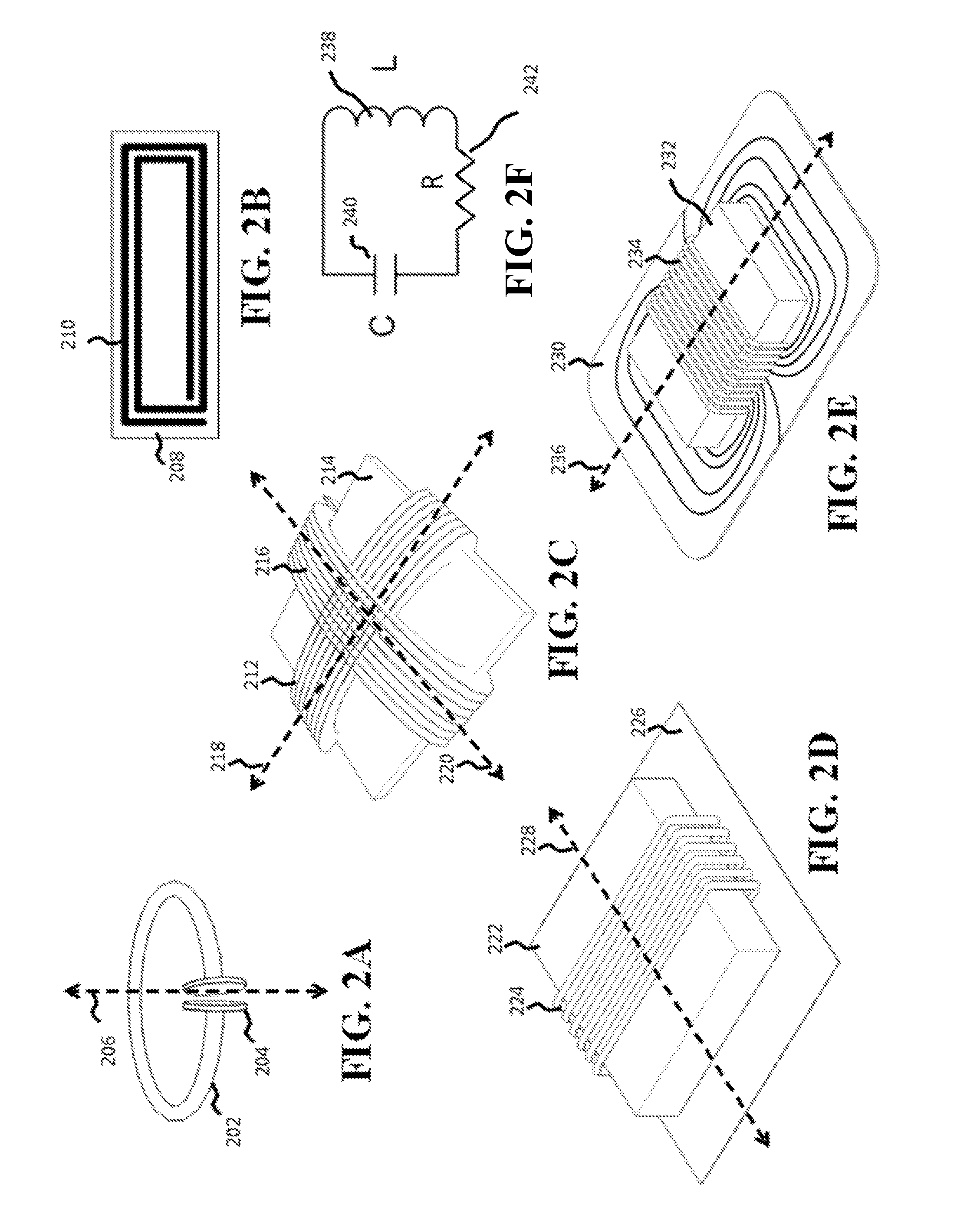
[0047]Wireless energy transfer systems described herein may be implemented using a wide variety of resonators and resonant objects. As those skilled in the art will recognize, important considerations f...


PUM


Abstract

A wireless energy transfer system includes wirelessly powered footwear. Device resonators in footwear may capture energy from source resonators. Captured energy may be used to generate thermal energy in the footwear. Wireless energy may be generated by wireless warming installations. Installations may be located in public locations and may activate when a user is near the installation. In some cases, the warming installations may include interactive displays and may require user input to activate energy transfer.

Description

CROSS REFERENCE TO RELATED APPLICATIONS[0001]This application claims the benefit of the following applications each of which is hereby incorporated by reference in its entirety: U.S. Provisional Application No. 61 / 818,149 filed on May 1, 2013; U.S. Provisional Application 61 / 823,974, filed on May 16, 2013; U.S. Provisional Application No. 61 / 825,937 filed on May 21, 2013; U.S. Provisional Application No. 61 / 825,942 filed on May 21, 2013; U.S. Provisional Application No. 61 / 826,230 filed on May 22, 2013; U.S. Provisional Application No. 61 / 839,262 filed on Jun. 25, 2013; and U.S. Provisional Application No. 61 / 861,097 filed on Aug. 1, 2013. The entire contents of each of the foregoing applications are incorporated by reference herein.BACKGROUND OF THE INVENTION[0002]Energy or power may be transferred wirelessly using a variety of known radiative, or far-field, and non-radiative, or near-field, techniques as detailed, for example, in commonly owned U.S. patent application Ser. No. 12 / ...

Claims


Application Information

Patent Timeline
IPC IPC(8): H04B5/00H01F38/14
CPCH04B5/0037H01F38/14A43B3/0015A43B7/02H04B5/0043H05B6/02H04B5/0075A43B7/04H02J5/00H02J50/12H02J7/0042H02J50/40H02J50/50A43B3/38A43B3/35H02J50/90H02J50/80
Inventor MUHS, JEFFREYGILCHRIST, AARONSEALY, KYLEE D.KURS, ANDRE B.MCCAULEY, ALEXANDER P.KESLER, MORRIS P.HALL, KATHERINE L.GUCKAYA, GOZDE
Owner WITRICITY CORP
Why Eureka
Try Eureka