Method for Crosstalk and Power Optimization in Silicon Photonic Based Switch Matrices

a technology of photonic based switches and power optimization, applied in the field of photonic integrated circuits, can solve the problems of photonic elements that exhibit non-ideal performance, degrade network performance, and portion of signals, and achieve the effect of suppressing crosstalk propagation

Inactive Publication Date: 2014-11-06
HUAWEI TECH CO LTD
View PDF4 Cites 19 Cited by
  • Summary
  • Abstract
  • Description
  • Claims
  • Application Information

AI Technical Summary

Benefits of technology

[0006]In accordance with an embodiment, a photonic switching fabric is provided. In this example, the photonic switching fabric includes a plurality of input ports, a plurality of output ports, and a plurality of photonic elements coupled between the input ports and the output ports. The photonic switching fabric further includes a control plane adapted to configure the photon

Problems solved by technology

In practice, the photonic elements exhibit non-ideal performance such that at least a portion of the signal leaks over to the non-selected output.
Signal leakage across the individual photon

Method used


Image

  • Method for Crosstalk and Power Optimization in Silicon Photonic Based Switch Matrices
  • Method for Crosstalk and Power Optimization in Silicon Photonic Based Switch Matrices
  • Method for Crosstalk and Power Optimization in Silicon Photonic Based Switch Matrices

Examples


Embodiment Construction

[0032]The making and using of embodiments of this disclosure are discussed in detail below. It should be appreciated, however, that the present invention provides many applicable inventive concepts that can be embodied in a wide variety of specific contexts. The specific embodiments discussed are merely illustrative of specific ways to make and use the invention, and do not limit the scope of the invention.

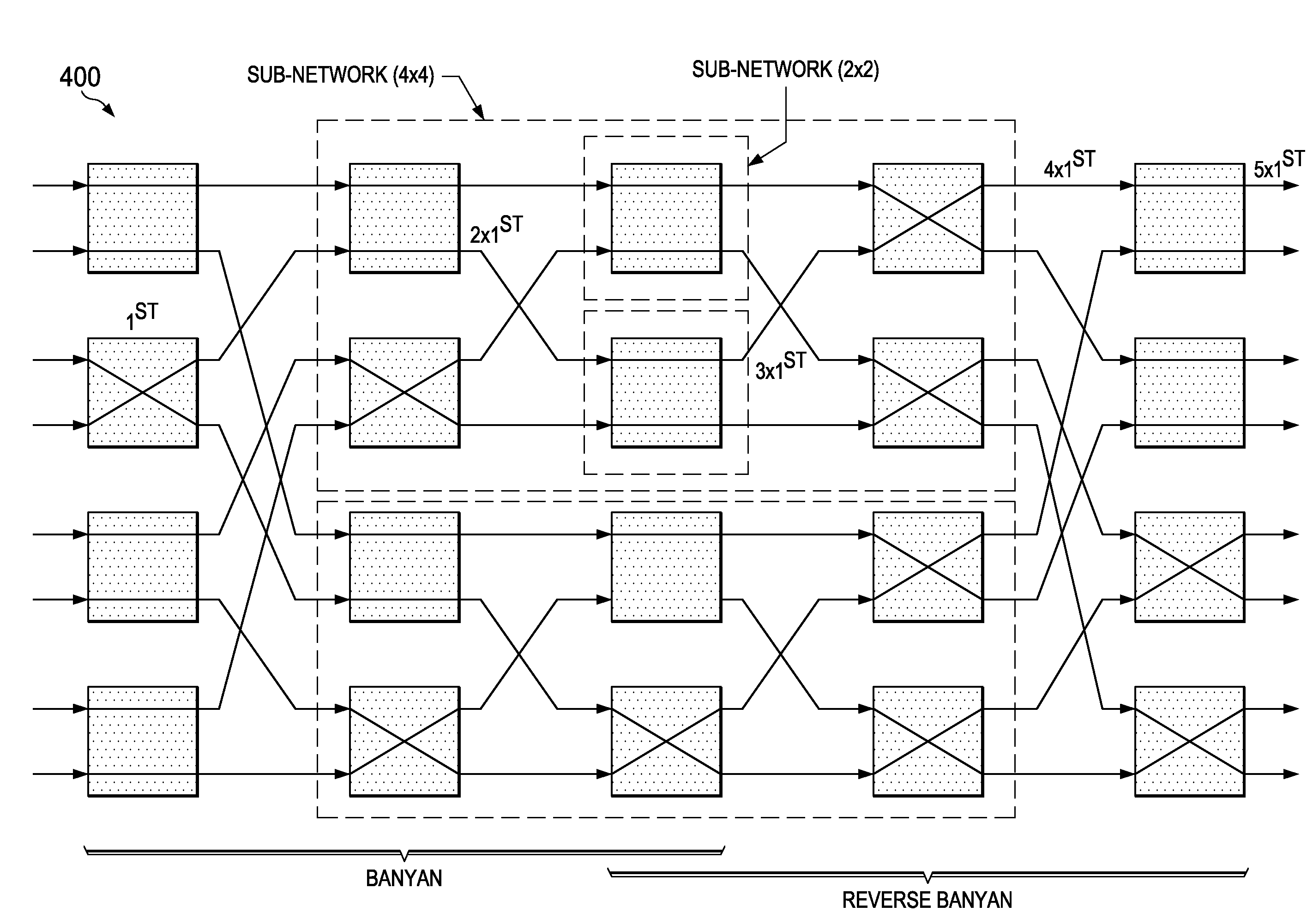
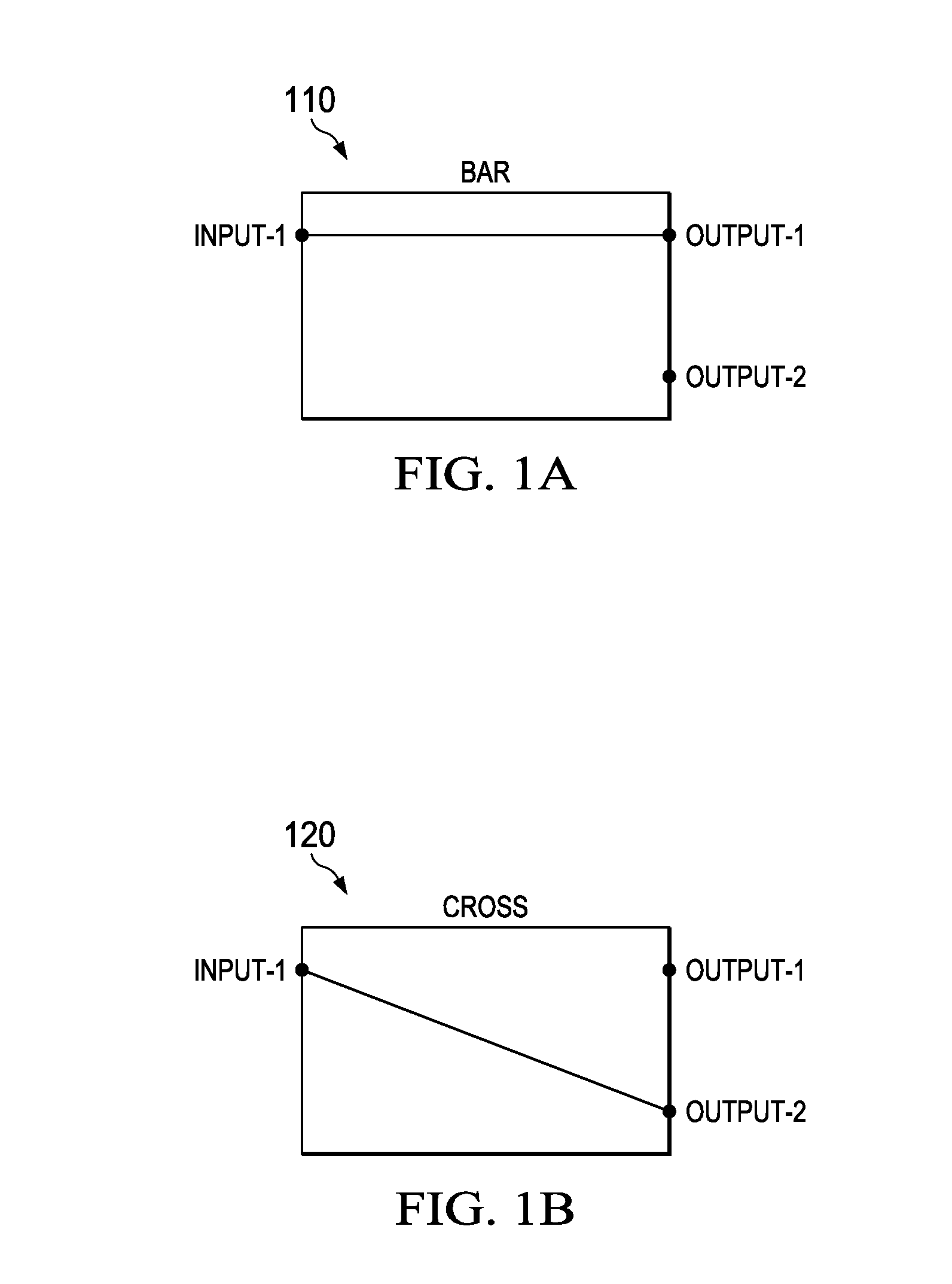
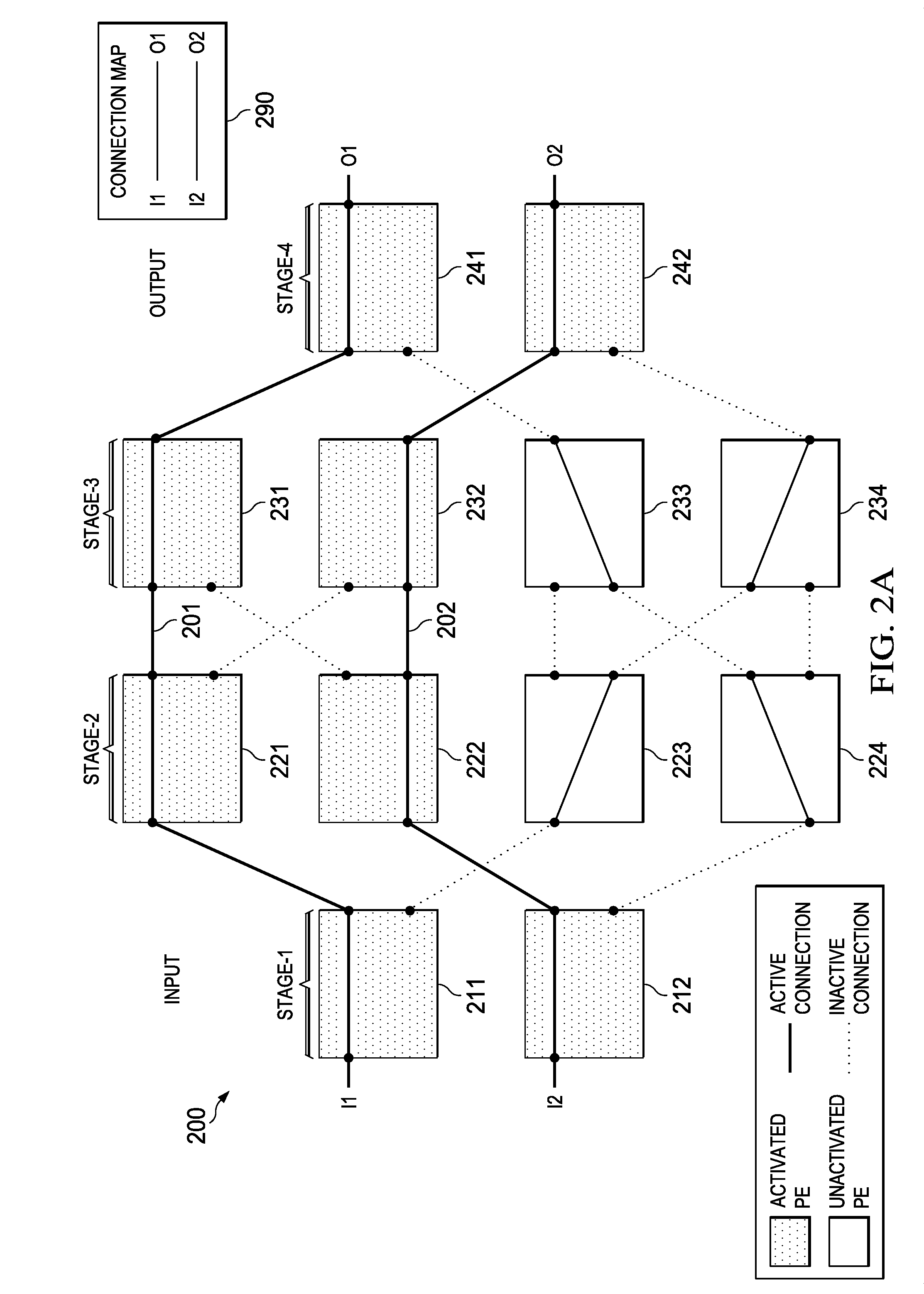
[0033]Photonic elements operate in either an active (i.e., powered) mode or an inactive (i.e., unpowered) mode depending on whether a power signal is being supplied. In the active mode, the switching configuration of the photonic element is selected by the operator to determine which output is connected to the input. In the inactive state, the switching configuration is not determined by the operator, and instead varies depending on environmental conditions (e.g., temperature, time, etc.) and / or characteristics of the photonic element. Conventional photonic switching fabrics are c...


PUM


Abstract

Crosstalk can be suppressed in photonic switching fabrics by activating unused photonic elements in a manner that manipulates the inactive connections and inhibits the propagation of cross-talk over the switching fabric. For example, unused photonic elements can be set to a cross or bar configuration to block first and second order crosstalk from propagating to the output ports, thereby reducing noise in the output signals. All of the unused elements can be activated in order to maximize crosstalk suppression. Alternatively, fewer than all of the unused elements may be activated to achieve a balance between crosstalk suppression and power conservation. Photonic switch architectures can be configured to use pre-determined cross-talk suppression maps (e.g., patterns of activated unused cells) for the various switching configurations, which may be computed using a recursive algorithm.

Description

[0001]This application claims the benefit of U.S. Provisional Application No. 61 / 818,296 filed on May 14, 2013, entitled “Method for Crosstalk and Power Optimization in Silicon Photonic Based Switch Matrices,” which is incorporated herein by reference as if reproduced in its entirety.TECHNICAL FIELD[0002]The present invention relates to Photonic Integrated Circuits (PICs), and, in particular embodiments, to methods for crosstalk and power optimization in silicon photonic based switches.BACKGROUND[0003]Modern day optical networks may use N×N photonic switching fabrics to interconnect inputs and outputs in central offices and other network switching locations. The N×N photonic switching fabrics may include multiple passive silicon photonic elements. By way of example, an 8×8 photonic switch may include a total of 112 1×2 photonic elements with half of them is 1×2 and the other half is 2×1. In practice, the photonic elements exhibit non-ideal performance such that at least a portion of...

Claims


Application Information

Patent Timeline
IPC IPC(8): H04L12/947
CPCH04L49/25H04Q11/0005H04Q2011/0049H04Q2011/0054
Inventor MEHRVAR, HAMIDQIAN, YIDUMAIS, PATRICKGOODWILL, DOMINICBERNIER, ERIC
Owner HUAWEI TECH CO LTD
Why Eureka
Try Eureka