
Individual monitoring of compression for mammographic examinations

Active Publication Date: 2014-11-06
KONINKLJIJKE PHILIPS NV
View PDF2 Cites 36 Cited by
  • Summary
  • Abstract
  • Description
  • Claims
  • Application Information

AI Technical Summary

Benefits of technology

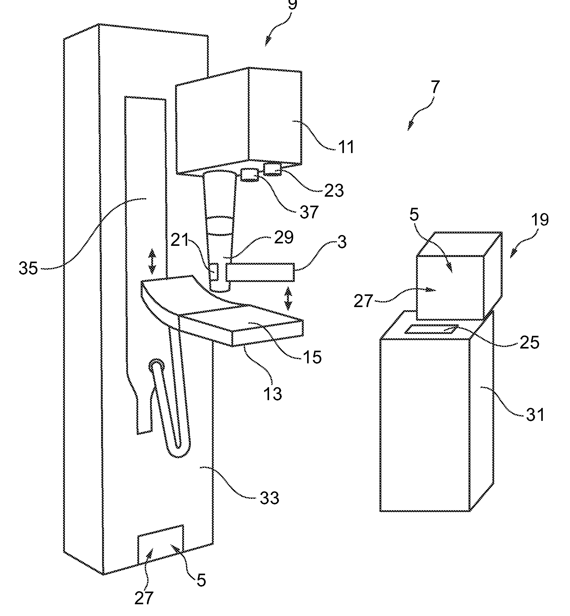
The present invention provides a method and system for individually monitoring the compression force during mammographic examination. This includes determining the breast contact area and calculating the compression force limit based on the breast contact area. The output signal provides a visual or auditory indication of whether the current compression force is appropriate for the breast under examination. The system includes a monitoring device, a tracking device, and a support plate for the breast. The invention allows for personalized guidance for breast compression and improves the accuracy and precision of mammographic examination.

Problems solved by technology

However, the compression often causes discomfort.

Method used


Image

  • Individual monitoring of compression for mammographic examinations
  • Individual monitoring of compression for mammographic examinations
  • Individual monitoring of compression for mammographic examinations

Examples


Embodiment Construction

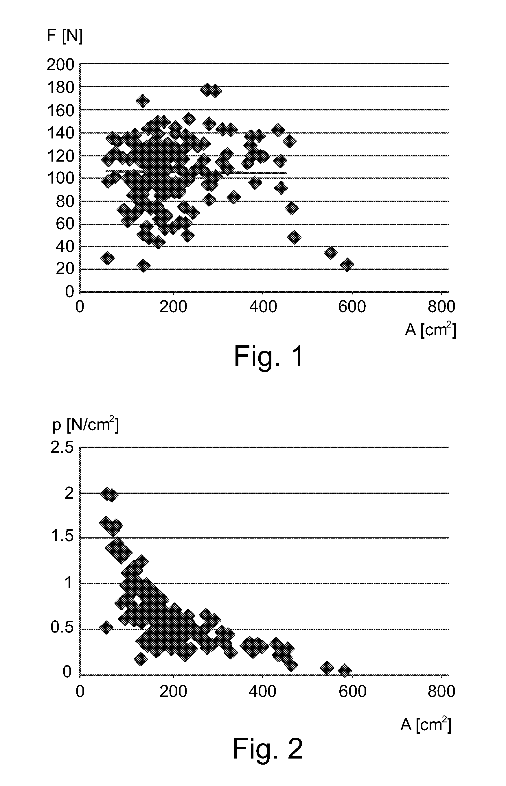
[0033]In FIG. 1 a graph is shown in which a known technique of applying a compression force during mammographic examination is represented. According to this technique the compression force depends on a compression height of the breast, i.e. on a distance between two plates between which the breast is positioned. The compression force is increased as long as the compression height of the breast decreases, i.e. as long as the breast is still pliable.

[0034]The compression causes pain sensations for the person under examination and leads to a reduced readiness to participate in mammographic screenings. The pain sensation may vary from person to person. FIG. 1 and FIG. 2 may partially explain the different pain sensations.

[0035]The graph in FIG. 1 shows the results of such a compression control which depends on the experience and subjective decisions of a user such as an assistant medical technician (AMT) or a radiology assistant. The y-axis shows the compression force F in Newton (N) a...


PUM

PropertyMeasurementUnit
compression forceaaaaaaaaaa

Abstract

The present invention relates to mammography. In particular, the present invention relates to a method and a corresponding system for individually monitoring a compression force in an apparatus for mammographic examination for personalized compression guidance. In order to provide a personalized guidance for the compression of the breast in a first step (S1a, S1b, S1c) a breast contact area (A) between a breast under examination and a compression plate (3) or a support plate (15) is determined. In a next step (S5) a compression force limit is determined based on the breast contact area (A). Then, in a further step (S9a, S9b, S9c) an output signal (5) representative of the relation between the breast contact area (A) and the compression force limit is provided to a user such that the user may decide whether to complete or to continue the application of compression force.

Description

FIELD OF THE INVENTION[0001]The present invention relates to mammography. In particular, the present invention relates to a method and a corresponding system for individually monitoring a compression force in an apparatus for mammographic examination for personalized compression guidance. Furthermore, the present invention relates to a computer program element and a computer readable medium.BACKGROUND OF THE INVENTION[0002]Mammography information is used for example for breast cancer screening. During mammography a breast under examination is mechanically compressed and subsequently a radiographic image of the flattened breast tissue is acquired. The mechanical compression of the breast prevents motion artefacts in the images. Moreover, the compression helps to obtain a homogeneous breast tissue thickness and to spread breast structures.[0003]The compression is usually controlled by a compression force which may for example be equal for each patient. According to the European Guidel...

Claims


Application Information

Patent Timeline
Patent Type & Authority Applications(United States)
IPC IPC(8): A61B6/00G01L1/26
CPCA61B6/548A61B6/502G01L1/26A61B6/0414
Inventor ERHARD, KLAUSMAACK, HANNS-INGOLOEPRICH, ANDREASWIEBERNEIT, NATALY
Owner KONINKLJIJKE PHILIPS NV
Learn More