Antenna Environment Sensing Device

a sensing device and environment technology, applied in the direction of transmission monitoring, receiver monitoring, electrical equipment, etc., can solve the problems of poor battery life of wireless communication devices, affecting the user experience of those devices, and changing the impedance of the antenna

Inactive Publication Date: 2014-11-06
COMMSENSE
View PDF21 Cites 28 Cited by
  • Summary
  • Abstract
  • Description
  • Claims
  • Application Information

AI Technical Summary

Problems solved by technology

Poor battery life in wireless communication devices is detrimental to the user experience with those devices.
One contributing factor to poor battery life is the changing of the impedance of the antenna due to the antenna's environment.
The internal placement of the antenna in modern wireless communication devices often results in a pronounced negative impact on the user experience.
The constantly changing impedance of the antenna leads to energy losses in the transmission and reception of radio signals by the wireless communication device.
These losses can be significant and result in severe degradation in the battery life of modern wireless communication devices.
In extreme cases, holding the wireless communication device in a certain way can cause a total loss of signal which may result in, at best, breaks in call audio transmission and, at worst, the complete dropping of a connection and loss of call audio transmission.
Prior attempts to rectify the issues associated with internal antenna placement have not been successful for a variety of reasons.
For example, while a complex antenna array may be implemented to improve signal performance, these configurations are expensive both in economic cost, internal phone real estate, and power consumption of the device.
In such cases, while the circuitry may rectify some of the issues associated with antenna performance in a small set of detectable use cases, the circuitry cannot detect all use cases and realized performance gains come at the cost of overall signal degradation introduced by the presence of the circuitry itself to detect the occurrence of a use case.

Method used


Image

  • Antenna Environment Sensing Device
  • Antenna Environment Sensing Device
  • Antenna Environment Sensing Device

Examples


Embodiment Construction

[0015]The Figures and the following description relate to various embodiments by way of illustration only. It should be noted that from the following discussion, alternative embodiments of the structures and methods disclosed herein will be readily recognized as viable alternatives that may be employed without departing from the principles of the embodiments.

[0016]Reference will now be made in detail to several embodiments, examples of which are illustrated in the accompanying figures. Wherever practicable, similar or like reference numbers may be used in the figures and may indicate similar or like functionality. The figures depict embodiments for purposes of illustration only.

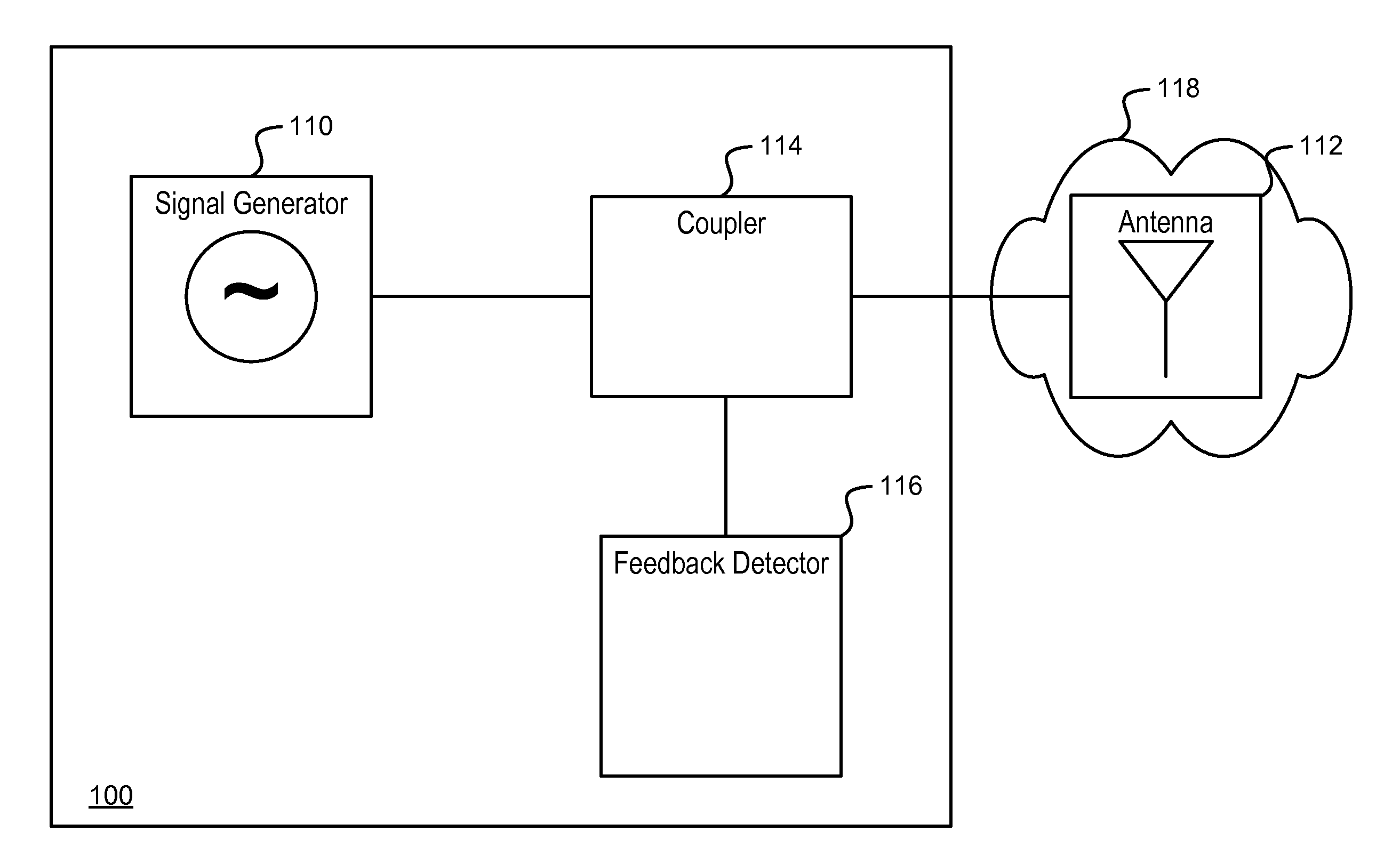
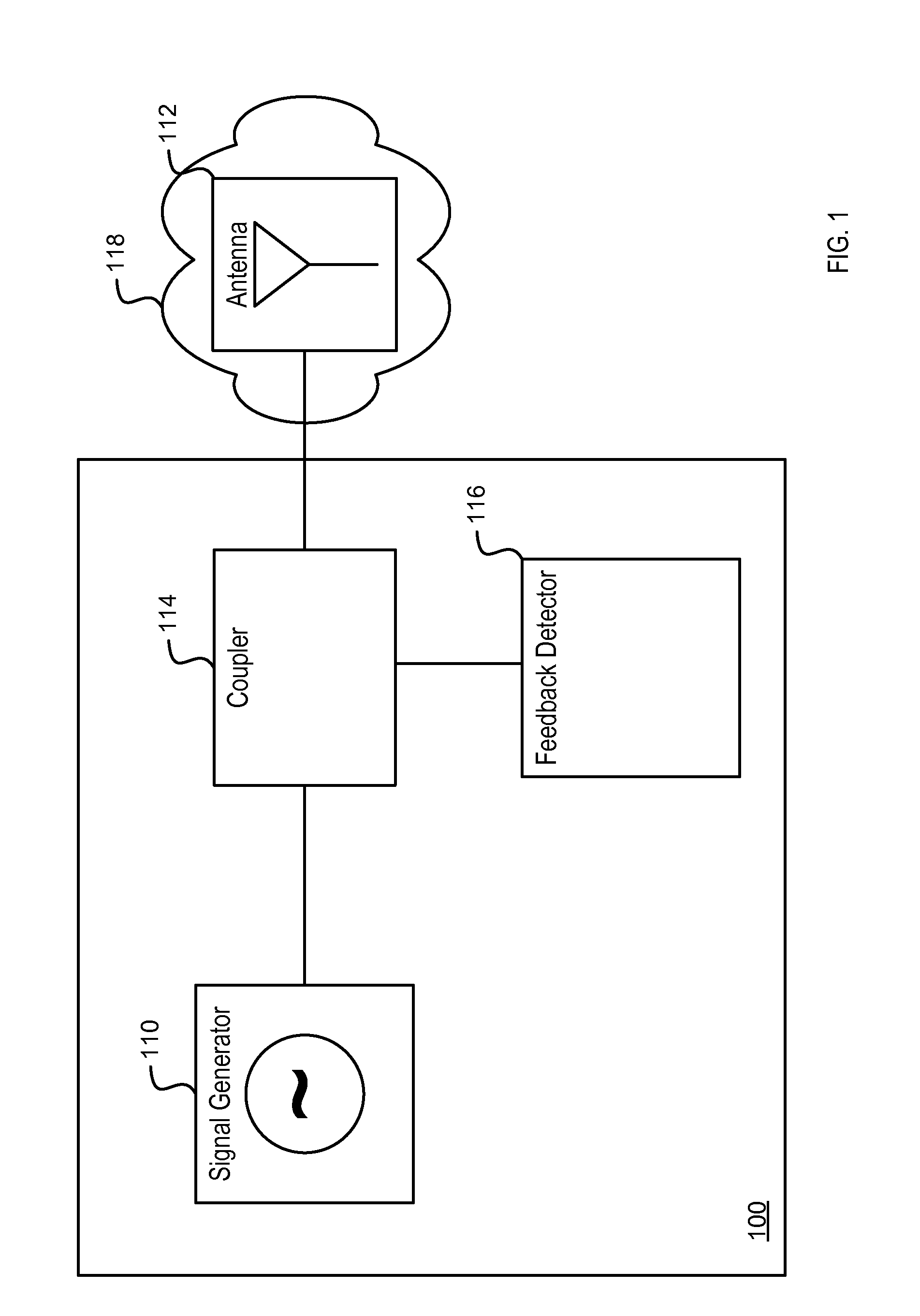
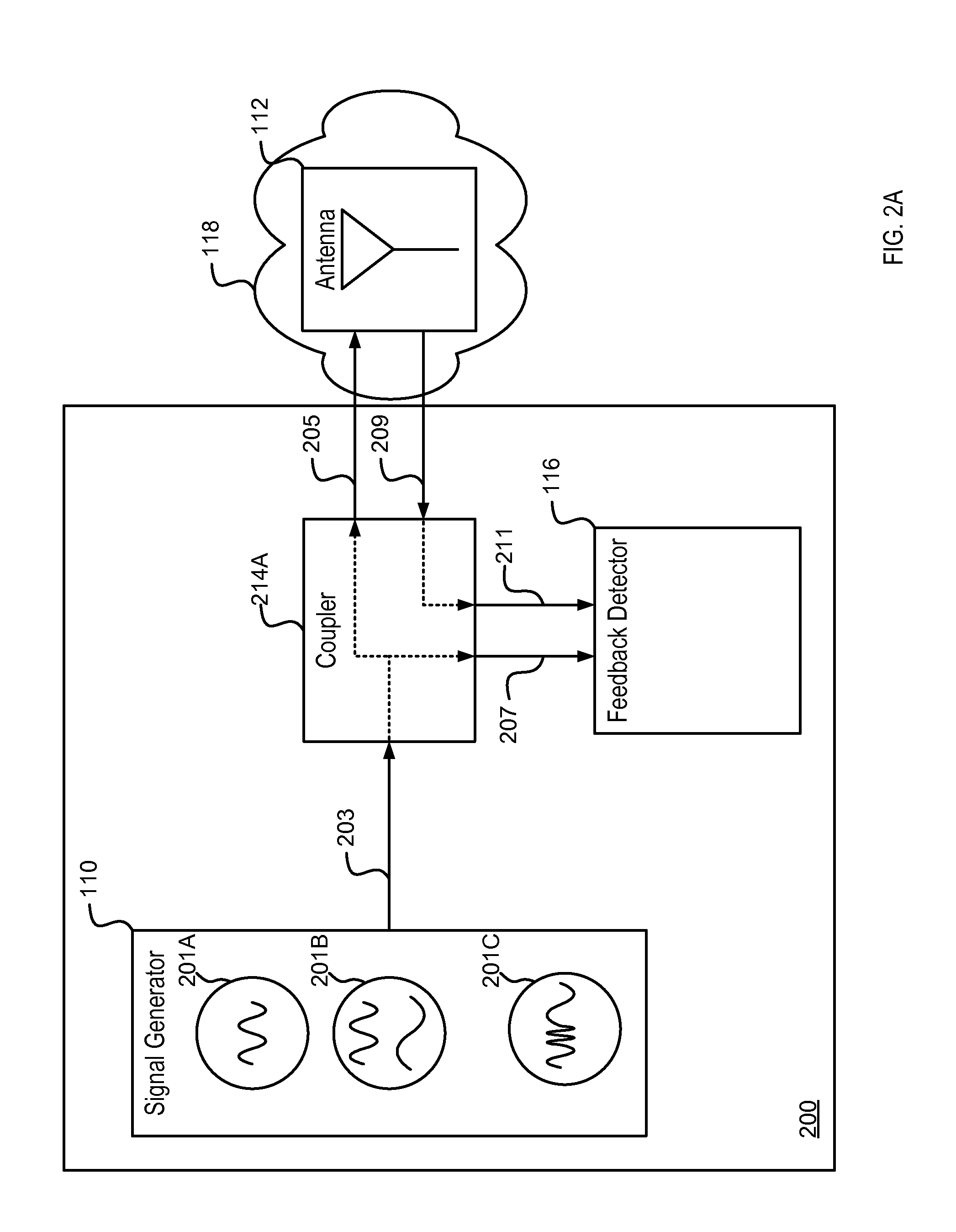
[0017]Embodiments relate to a sensing device configured to sense the environment of an antenna in a wireless communications device without impacting data signal integrity. By incorporating a sensing device in the wireless communications device that operates outside the data signal operating frequency(s) of th...


PUM


Abstract

Embodiments relate to a sensing device configured to sense the environment of an antenna in a wireless communications or wireless power transfer device without impacting data signal or transferred power integrity. By incorporating a sensing device in the wireless device that operates outside the data signal operating and operational power transfer frequency(s) of the antenna, send/receive data signal integrity may be retained while sensing the environment of the antenna. The sensing device may further use properties of the sensed environment to adjust the configuration of a tunable antenna to decrease signal degradation due to the environment and increase battery life or power transfer efficiency of the wireless device.

Description

CROSS-REFERENCE TO RELATED APPLICATIONS[0001]This application claims the benefit of U.S. Provisional Application 61 / 818,931 filed on May 3, 2013, which is incorporated by reference herein in its entirety.BACKGROUND OF THE INVENTION[0002]1. Field[0003]This disclosure relates to a device for sensing the environment of an antenna and more specifically to sensing properties of the environment by measuring feedback from the antenna.[0004]2. Description of the Related Art[0005]Poor battery life in wireless communication devices is detrimental to the user experience with those devices. One contributing factor to poor battery life is the changing of the impedance of the antenna due to the antenna's environment. Whereas wireless communication devices previously utilized efficient external fixed or extendable antennas or were coupled to remote mounted antennas such as in the case of car phones, most modern wireless communication devices feature internal antennas for aesthetic reasons. The int...

Claims


Application Information

Patent Timeline
Patent Type & Authority Applications(United States)
IPC IPC(8): H04B17/00
CPCH04B17/0067H04B17/24H04B17/0085H04B17/12
Inventor KOVACS, ANDREW STEPHENALLEN, WESLEY NATHANIEL
Owner COMMSENSE
Why Eureka
Try Eureka