Mast lift with screw drive and gas strut

a screw drive and mast lift technology, applied in the field of personnel lifts, can solve the problems of cumbersome and difficult maneuverability of existing ladders, limited work area of users, and difficulty in maneuvering conventional ladders, and achieve the effect of low weigh

a screw drive and mast lift technology, applied in the field of personnel lifts, can solve the problems of cumbersome and difficult maneuverability of existing ladders, limited work area of users, and difficulty in maneuvering conventional ladders, and achieve the effect of low weigh

US20140332317A1Active Publication Date: 2014-11-13JLG IND INC

Image

  • Mast lift with screw drive and gas strut
  • Mast lift with screw drive and gas strut
  • Mast lift with screw drive and gas strut

Examples


Embodiment Construction

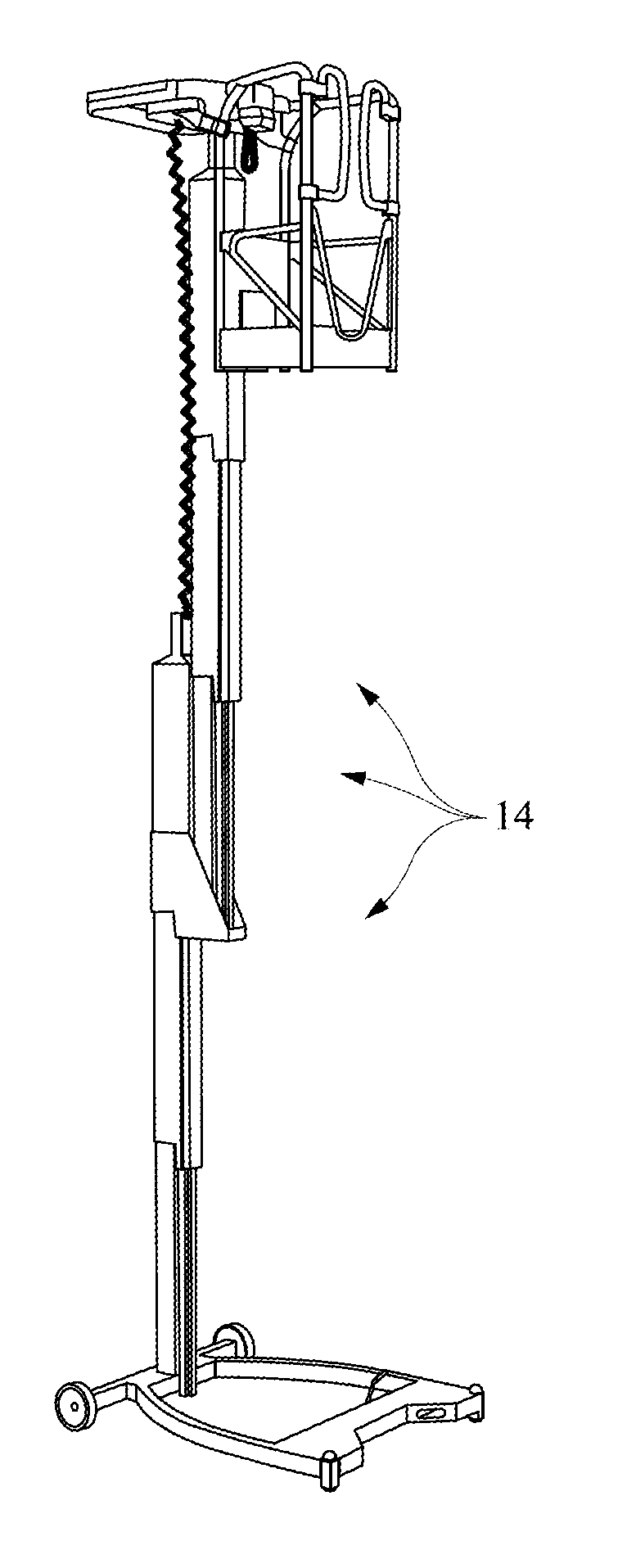
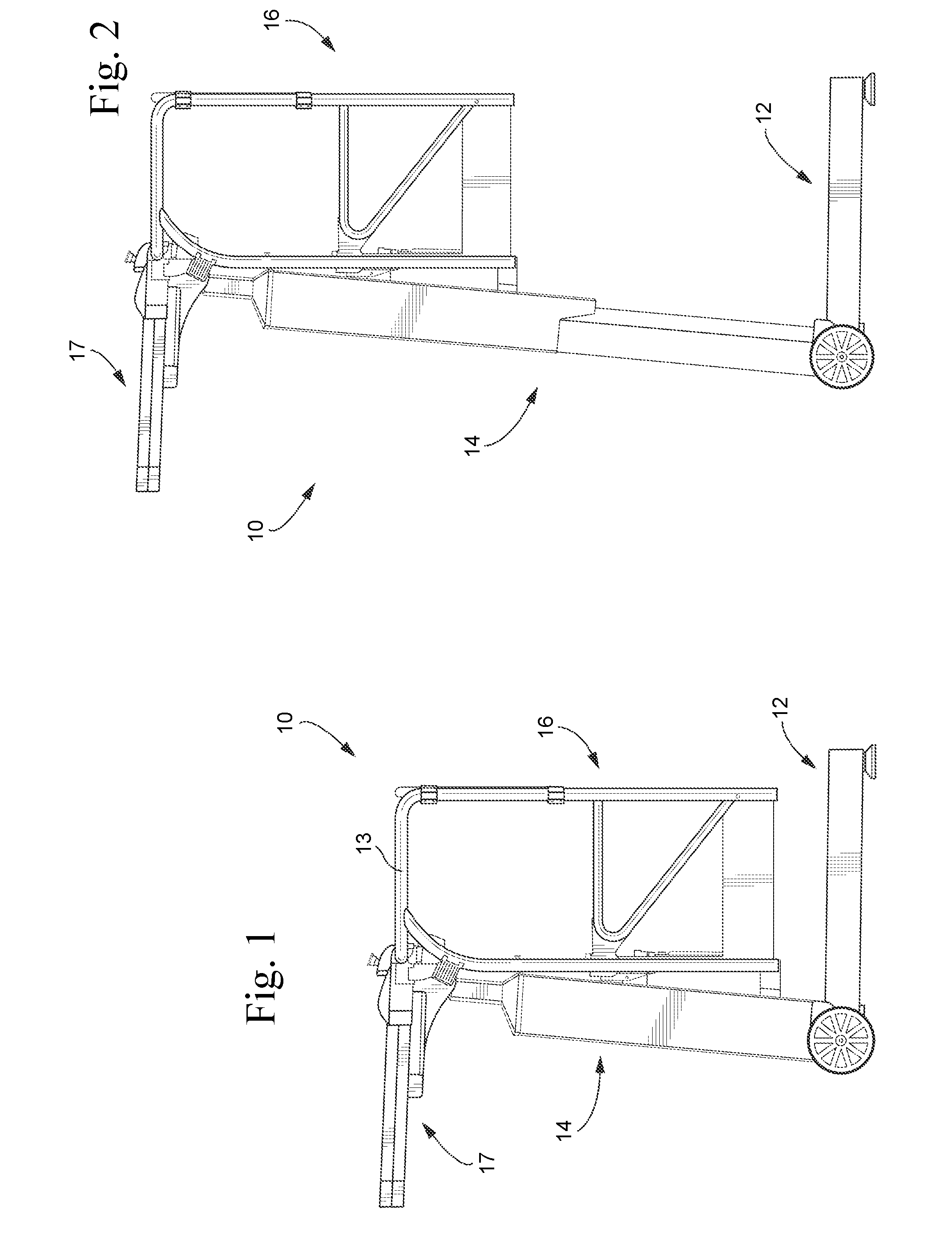
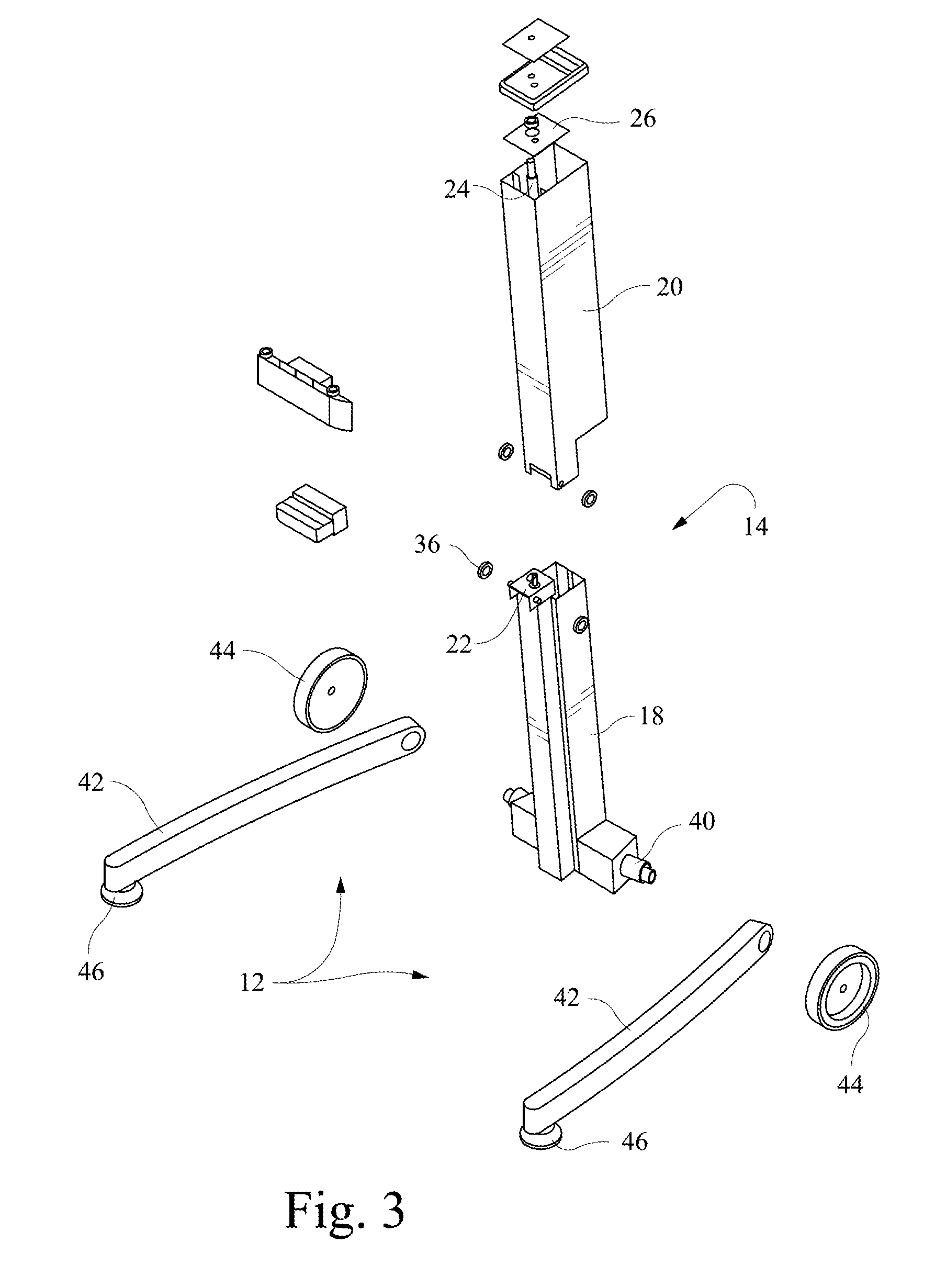
[0024]With reference to FIGS. 1-4, a mast lift 10 includes a base 12 and a telescoping mast 14 coupled with the base 12 and extending upward from the base 12. A platform 16 is secured to a movable section of the telescoping mast 14. A lifting assembly is connected between the base 12 and the platform 16 and moves the platform 16 between a lowered position (FIG. 1) and a raised position (FIG. 2). The platform 16 includes a safety rail 13 and a gate 15. Additionally, an accessory tray 17 may be connected to the platform 16. Other or alternative accessory items may be attached. For example, the design can be customized with specific accessories for a specific user purpose, i.e., the machine may designed such that it can accommodate a number of accessories specific to user requirements, including tool trays, buckets, drawers, paint trays, cleaning, and other accessories. These accessories may be attached to the mast, base or platform.

[0025]The telescoping mast 14 is provided with a supp...


PUM


Abstract

A mast lift includes a base and a telescoping mast coupled with the base and extending upward from the base. The telescoping mast has a support section fixed to the base and a movable section movably connected and displaceable relative to the support section between a retracted position and an extended position. A top cap is secured to the movable section, and a platform is supported by the top cap and the movable section. A gas strut acts between the support section and the movable section and biases the movable section toward the extended position. A threaded driving rod is connected between the top cap and the base and extends through a fixed nut assembly.

Description

CROSS-REFERENCES TO RELATED APPLICATIONS[0001]This application is a continuation-in-part (CIP) of U.S. Patent application Ser. No. 13 / 191,676, filed Jul. 27, 2011, pending, which claims the benefit of U.S. Provisional Patent Application No. 61 / 374,368, filed Aug. 17, 2010, the entire contents of each of which are hereby incorporated by reference in this application.STATEMENT REGARDING FEDERALLY SPONSORED RESEARCH OR DEVELOPMENT[0002](NOT APPLICABLE)BACKGROUND OF THE INVENTION[0003]The present invention relates to a personnel lift and, more particularly, to a portable lift machine including a work platform raised and lowered by a lifting system. The LiftPod® system by JLG Industries, Inc. has been described in U.S. patent application Ser. No. 10 / 594,666, U.S. patent application Ser. No. 11 / 581,785, U.S. patent application Ser. No. 12 / 190,217, U.S. patent application Ser. No. 12 / 293,759, U.S. Pat. No. D570,071, U.S. Pat. No. 7,614,459, U.S. Pat. No. 7,762,532, and U.S. Pat. No. 7,766,...

Claims


Application Information

Patent Timeline
13 Nov 2014
Publication
US20140332317A1
IPC
B66F11/04
CPC
B66F11/04; E04G1/22
Inventors
CAMPBELL, GEOFFREY GEORGE; WATSON, JASON JAMES