Smart watch and method for controlling the same

Active Publication Date: 2014-11-13
LG ELECTRONICS INC
View PDF9 Cites 88 Cited by
  • Summary
  • Abstract
  • Description
  • Claims
  • Application Information

AI Technical Summary

Benefits of technology

[0007]Accordingly, the disclosure is directed to a smart watch and a method for controlling the same t

Problems solved by technology

Although smart phones and tablet PCs may be conveniently used using user fingers or a touch pen, t

Method used


Image

  • Smart watch and method for controlling the same
  • Smart watch and method for controlling the same
  • Smart watch and method for controlling the same

Examples


first embodiment

[0051]FIG. 3 is a diagram illustrating a control method of a smart watch according to an embodiment of the disclosure. More specifically, FIG. 3 illustrates determination of the notification device in the smart watch worn mode when the smart watch 100 and the external digital device 200 are spaced by a distance d1 within a preset distance d.

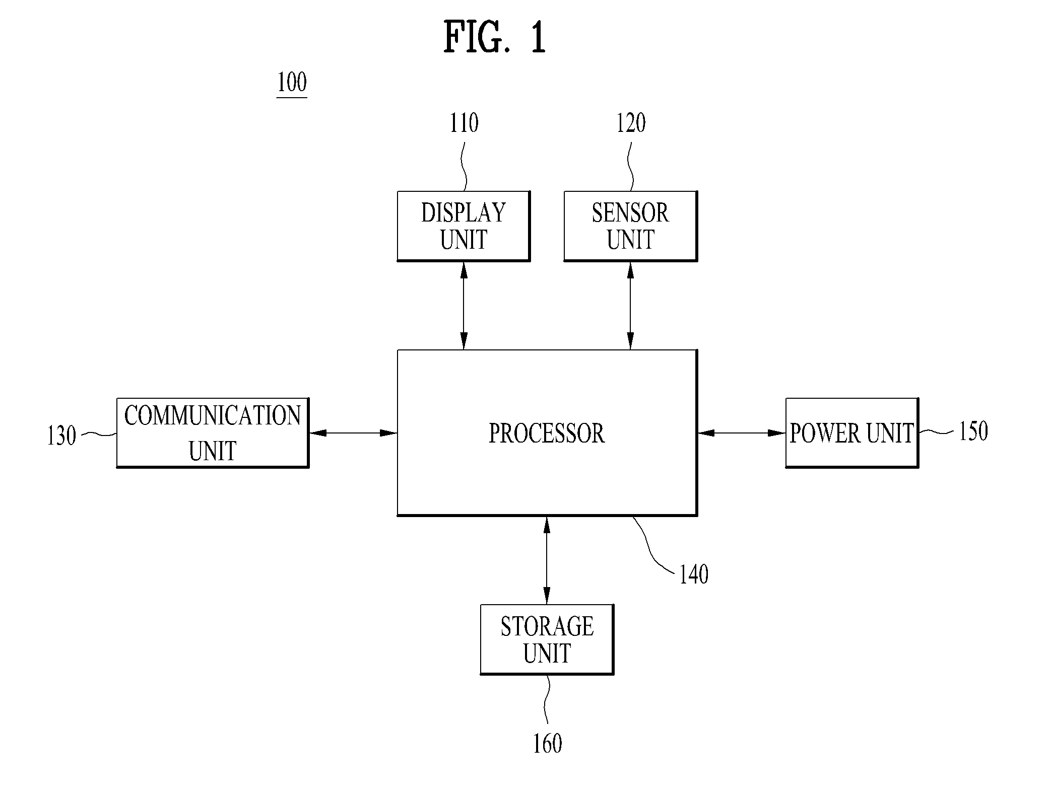
[0052]First, the smart watch 100 may detect the mode of the smart watch 100. The mode of the smart watch 100 may include a smart watch worn mode and a smart watch unworn mode. The mode of the smart watch 100 may be determined according to whether there is an input signal for the rear surface (not shown) of the smart watch 100 or whether there is an input signal for the buckle (not shown) of the smart watch 100, as described previously with reference to FIG. 1. For example, if the smart watch 100 detects an input signal from a user 10, i.e. a contact signal, at the rear surface (not shown) of the smart watch 100, the smart watch 100 may recognize ...

second embodiment

[0064]FIG. 5 is a diagram illustrating a control method of a smart watch according to an embodiment of the disclosure. More specifically, FIG. 5 illustrates determination of a notification device in the smart watch worn mode when the smart watch 100 and the external digital device 200 are separated by distance d2 exceeding a preset distance d.

[0065]First, the smart watch 100 may detect the mode of the smart watch 100. Referring to FIG. 5, the smart watch 100 may detect the worn mode. The smart watch 100 may detect the external digital device 200 paired therewith. Referring to FIG. 5, the smart watch 100 may detect the external digital device, i.e. a smart phone, paired therewith.

[0066]Next, the smart watch 100 may detect an event occurring in at least one of the smart watch 100 and the external digital device 200. Referring to FIG. 5, the occurred event may correspond to an incoming telephone call event occurring in at least one of the smart watch 100 and the external digital device...

third embodiment

[0069]FIG. 6 is a diagram illustrating a control method of a smart watch according to an embodiment of the disclosure. More specifically, FIG. 6 illustrates determination of the notification device in the smart watch unworn mode when the smart watch 100 and the external digital device 200 are distanced by a distance d1 within a preset distance d.

[0070]First, the smart watch 100 may detect the mode of the smart watch 100. Referring to FIG. 6, the smart watch 100 detects absence of an input signal for at least one of the rear surface (not shown) of the smart watch 100 and the buckle (not shown) of the smart watch 100. Accordingly, the smart watch 100 may detect a smart watch unworn mode. For example, if input signals for both the rear of the smart watch 100 and the buckle of the smart watch 100 are not detected, the smart watch 100 may determine the mode as the smart watch unworn mode. In addition, the smart watch 100 may detect an external digital device 200 paired therewith. Referri...


PUM


Abstract

Discussed are a smart watch and a method for controlling the same, which determine a notification device that provides a notification of an event, based on wearing/non-wearing of a smart watch and on a distance between the smart watch and an external digital device. The smart watch includes a display unit configured to display content, a sensor unit configured to detect an input signal and transmit the detected input signal to a processor, a communication unit configured to transmit/receive data, and the processor configured to control the display unit, the sensor unit, and the communication unit, wherein the processor is configured to detect a mode of the smart watch, wherein the mode of the smart watch includes a worn mode and an unworn mode of the smart watch.

Description

[0001]Pursuant to 35 U.S.C. §119(a), this application claims the benefit of Korean Patent Application No. 10-2013-0051503, filed on May 7, 2013, which is hereby incorporated by reference as if fully set forth herein.BACKGROUND OF THE INVENTION[0002]1. Field of the Invention[0003]The disclosure relates to a smart watch and a method for controlling the same, and more particularly, to a method for determining a notification device that provides a notification of an event, based on whether a smart watch is being worn or not and on a distance between the smart watch and an external digital device.[0004]2. Discussion of the Related Art[0005]With advances in technology, development of wearable computers has accelerated. Wearable computers refer to computers that a user can naturally wear like clothes, wristwatches, glasses, or accessories. Although smart phones and tablet PCs may be conveniently used using user fingers or a touch pen, they may be inconvenient in that the user has to put th...

Claims


Application Information

Patent Timeline
IPC IPC(8): G04G21/04
CPCG04G21/04G04C3/002H04B1/40G01B21/16G04B37/1486G04G21/06G04G21/08G06F3/041
Inventor PARK, HYORIMLEE, DOYOUNGKIM, YONGSIN
Owner LG ELECTRONICS INC
Why Eureka
Try Eureka