Structure for mounting battery pack on vehicle

a battery pack and vehicle technology, applied in the direction of batteries, cell components, battery/fuel cell control arrangements, etc., can solve the problems of reduced strength of the crossmember, and easy water ingress of the battery, so as to ensure the cooling performance of the battery and improve the comfort of the rear seat. , the effect of sufficient minimum ground clearan

Inactive Publication Date: 2014-11-20
HONDA MOTOR CO LTD
View PDF26 Cites 128 Cited by
  • Summary
  • Abstract
  • Description
  • Claims
  • Application Information

AI Technical Summary

Benefits of technology

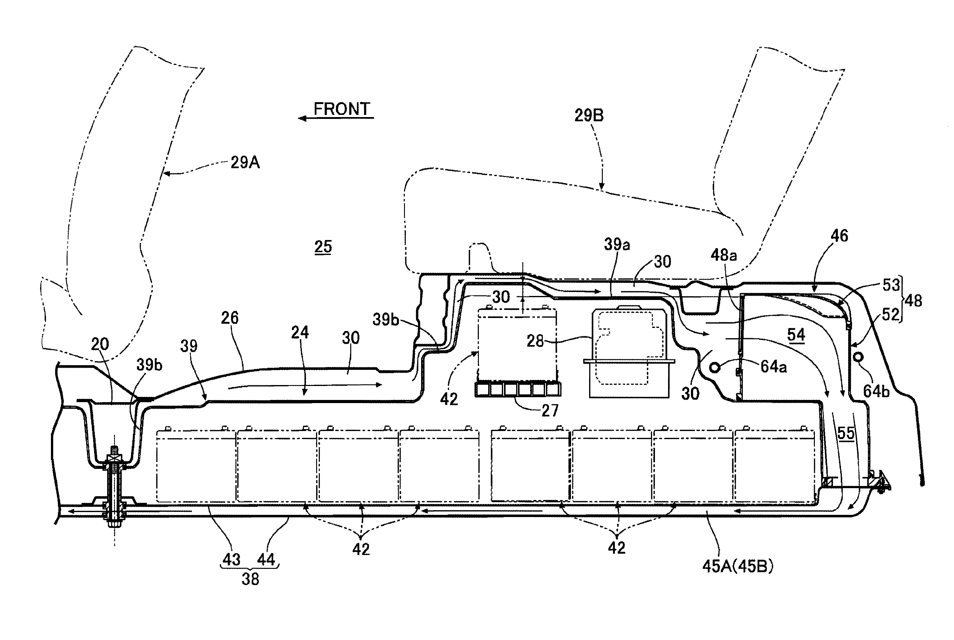
[0015]In accordance with the first aspect of the present invention, air in the space part formed between the lower face of the floor panel and the upper face of the battery case is sucked into the interior of the battery case via the cooling air suction member and, while flowing through the upstream side cooling passage extending forward of the cross member and the downstream side cooling passage extending from the downstream side of the upstream side cooling passage toward the cooling air discharge member, can cool the battery disposed thereabove. Since the recess portion, into which the cross member is fitted, is formed on the upper face of the battery case so as to extend in the vehicle width direction, it is possible to mount the battery pack on the vehicle body without interfering with the cross member, and it is unnecessary to raise the position of the cross member or form a cutout in the cross member, thereby enabling a balance to be achieved between the capacity of the vehicle compartment and the strength of the cross member while ensuring a sufficient minimum ground clearance for the battery pack and preventing the battery from becoming wet. Furthermore, since the recess portion is formed on the upper face of the battery case, the cooling passage disposed beneath the battery is not narrowed, thus ensuring the battery cooling performance.
[0016]Moreover, in accordance with the second aspect of the present invention, since the cooling air suction member is disposed higher than the cooling passage of the battery case, it is possible to raise the position of the cooling air suction member and make it difficult for wate

Problems solved by technology

In the above conventional arrangement, a tunnel part forming a cooling air passage in the interior of the battery case protrudes upwardly so as to intersect the recess portion of the battery case, and in order to avoid interference with this tunnel part, a recessed part (cutout) is formed on a lower face of the cross member fitted into the recess portion, but there is the problem that the strength of the crossmember is degraded by this recessed part.
If in order to avoid this the position of the cross member were to be raised, the capacity of a vehicle compartment would be

Method used


Image

  • Structure for mounting battery pack on vehicle
  • Structure for mounting battery pack on vehicle
  • Structure for mounting battery pack on vehicle

Examples


first embodiment

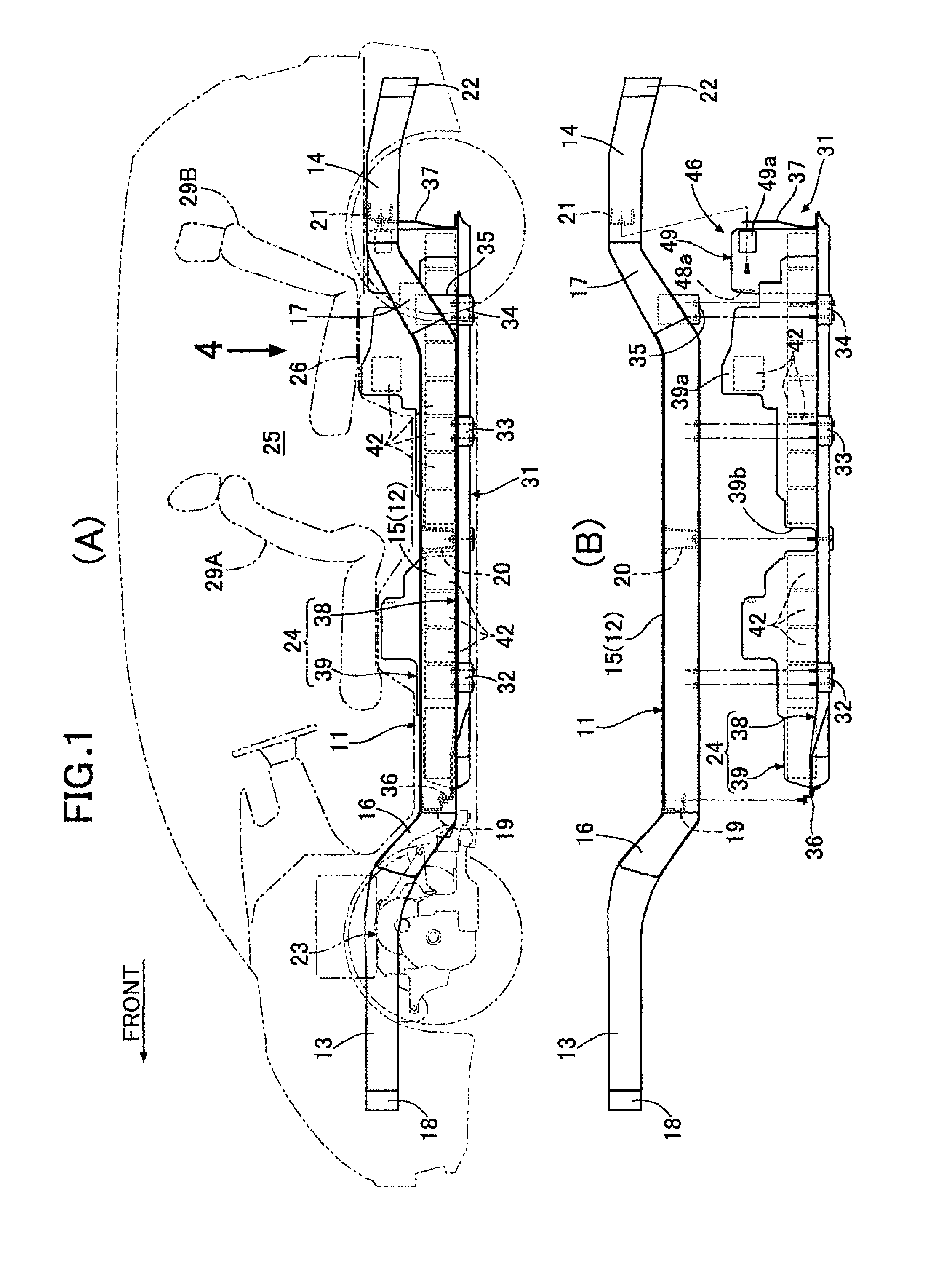
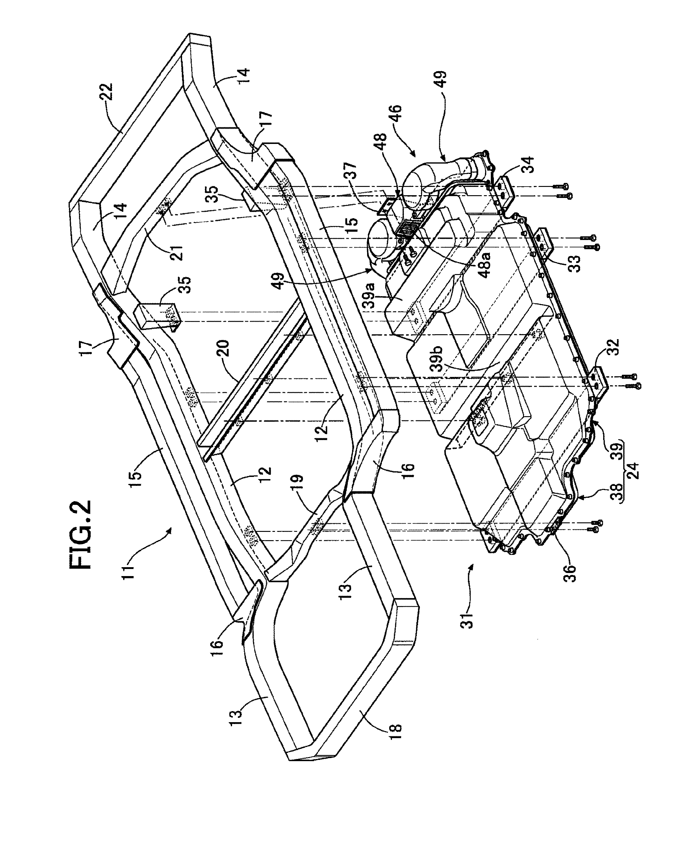
[0046]As shown in FIG. 1 and FIG. 2, a vehicle body frame 11 of an electric automobile includes a pair of left and right floor frames 12 and 12 extending in the vehicle body fore-and-aft direction, a pair of left and right front side frames 13 and 13 extending forwardly from the front ends of the floor frames 12 and 12 while bending upwardly, a pair of left and right rear side frames 14 and 14 extending rearwardly from the rear ends of the floor frames 12 and 12 while bending upwardly, a pair of left and right side sills 15 and 15 disposed outside, in the vehicle width direction, of the floor frames 12 and 12, a pair of left and right front outriggers 16 and 16 connecting the front ends of the side sills 15 and 15 to the front ends of the floor frames 12 and 12, a pair of left and right rear outriggers 17 and 17 connecting the rear ends of the side sills 15 and 15 to the rear ends of the floor frames 12 and 12, a front bumper beam 18 providing a connection between front end parts of...


PUM


Abstract

In a structure for mounting a battery pack on a vehicle, since a recess portion, into which a cross member is fitted, is formed on an upper face of a battery case so as to extend in a vehicle width direction, it is possible to mount the battery pack on a vehicle body without interfering with the cross member, and it is unnecessary to raise the position of the cross member or form a cutout in the cross member, thereby enabling a balance to be achieved between the capacity of a vehicle compartment and the strength of the cross member while ensuring a sufficient minimum ground clearance for the battery pack and preventing a battery from becoming wet. Furthermore, since the recess portion is formed on the upper face of the battery case, a cooling passage disposed beneath the battery is not narrowed, thus ensuring the battery cooling performance.

Description

TECHNICAL FIELD[0001]The present invention relates to a structure for mounting a battery pack on a vehicle in which the battery pack, which comprises a battery case that houses a plurality of batteries, a cooling air suction member that sucks cooling air into a cooling passage formed in an interior of the battery case, and a cooling air discharge member that discharges cooling air from the cooling passage, is disposed beneath a floor panel and a cross member that extends in a vehicle width direction.BACKGROUND ART[0002]An arrangement in which a groove-shaped recess portion extending in the vehicle width direction is formed on an upper face of a battery case of a battery pack of an electric automobile, and when the battery pack is mounted on a vehicle body from below, a cross member of the vehicle body extending in the vehicle width direction is fitted into the recess portion, is known from Patent Document 1 below.RELATED ART DOCUMENTSPatent Document[0003]Patent Document 1: Japanese ...

Claims


Application Information

Patent Timeline
IPC IPC(8): H01M10/6561H01M2/10B60K1/04H01M10/625B60K11/06B60L11/18H01M50/209H01M50/224H01M50/249H01M50/278
CPCB60L11/1874B60K1/04B60K11/06B60L11/1877H01M2220/20H01M10/5016H01M2/1083B60K2001/0422H01M10/5063H01M10/5071H01M2/1077H01M10/6565B60K2001/0438H01M10/6563H01M10/613B60K2001/0433H01M10/6561H01M10/5067H01M10/625H01M10/5004B60K2001/005B60L58/26B60L50/66Y02T10/70Y02E60/10H01M50/249H01M50/278H01M50/224H01M50/209
Inventor FUJII, RYOHOTOZUKA, YASUAKIYAMAMOTO, KOICHI
Owner HONDA MOTOR CO LTD
Why Eureka
Try Eureka