Headrest structure and headrest device

Active Publication Date: 2014-11-20
NHK SPRING CO LTD
View PDF17 Cites 11 Cited by
  • Summary
  • Abstract
  • Description
  • Claims
  • Application Information

AI Technical Summary

Benefits of technology

[0023]As explained above, the present invention enables easy

Problems solved by technology

However, the structure is complex, result in much effort being required for assembly.
Furthermore, movement of the guide

Method used


Image

  • Headrest structure and headrest device
  • Headrest structure and headrest device
  • Headrest structure and headrest device

Examples


Embodiment Construction

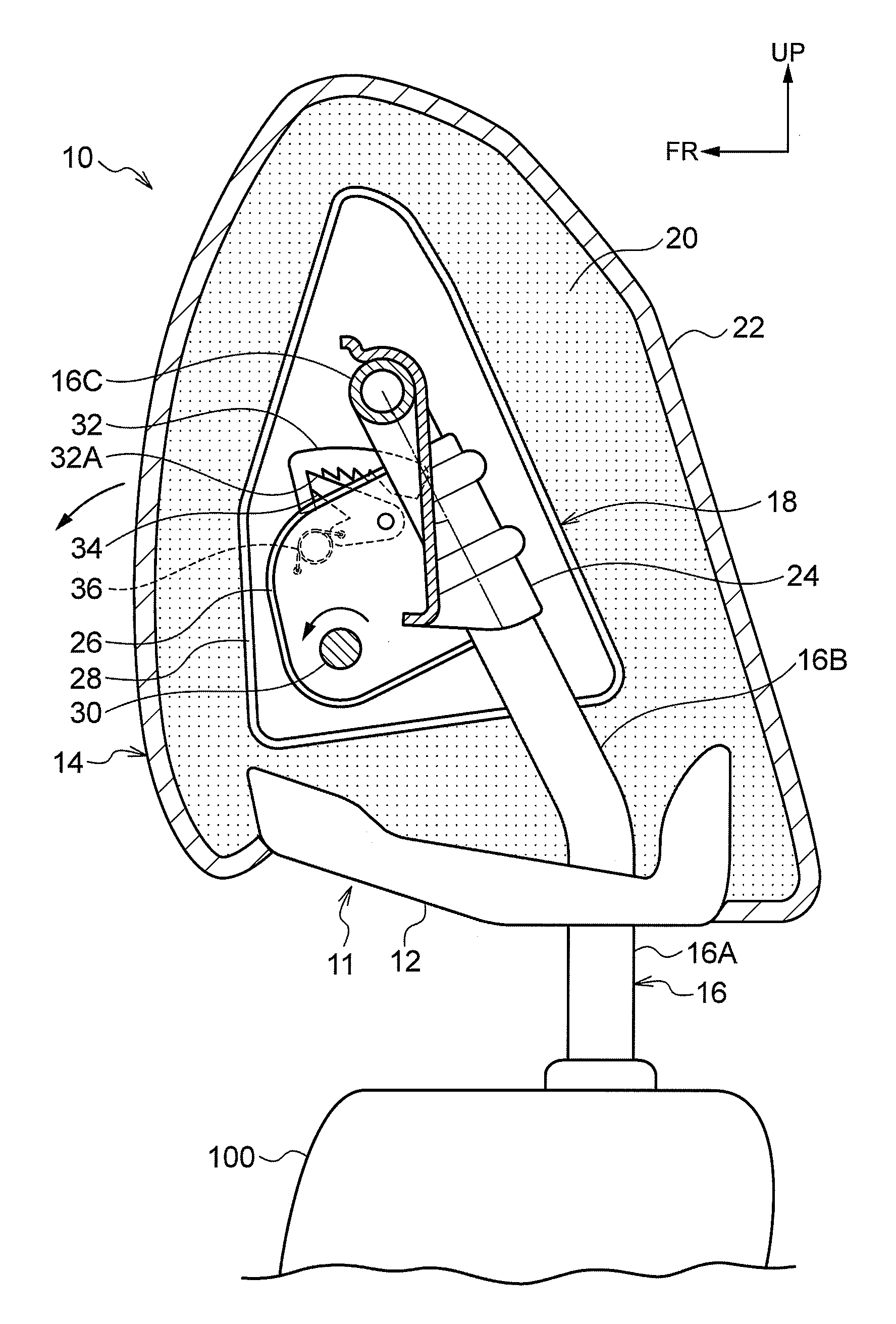
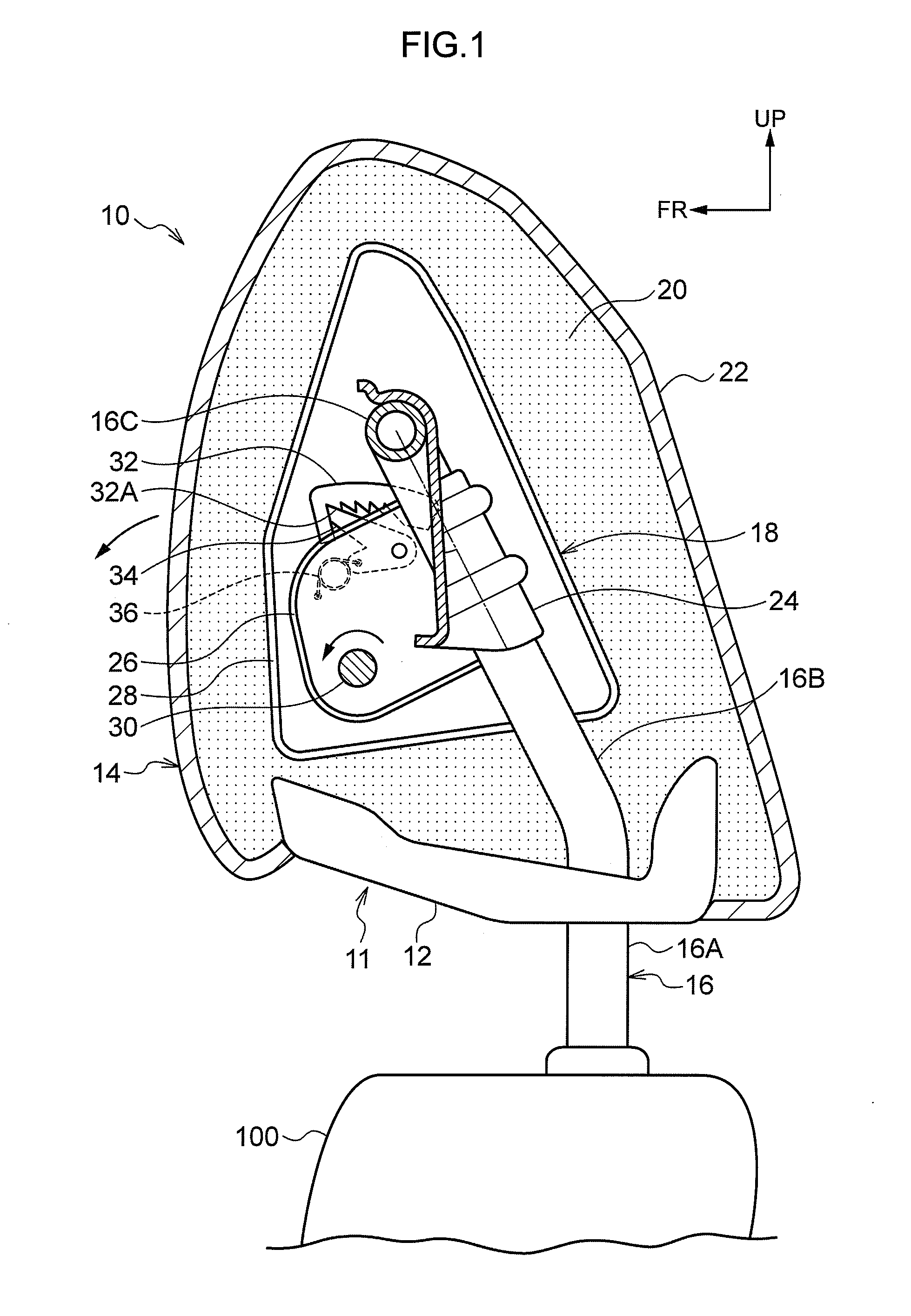
[0033]Explanation follows regarding an example of a headrest device 10 provided with a headrest structure 11 according to an exemplary embodiment of the present invention, with reference to the drawings. Note that, in the drawings, an arrow FR indicates a forward direction of a seat, an arrow UP indicates an upward direction of the seat and an arrow RH indicates a right direction of the seat.

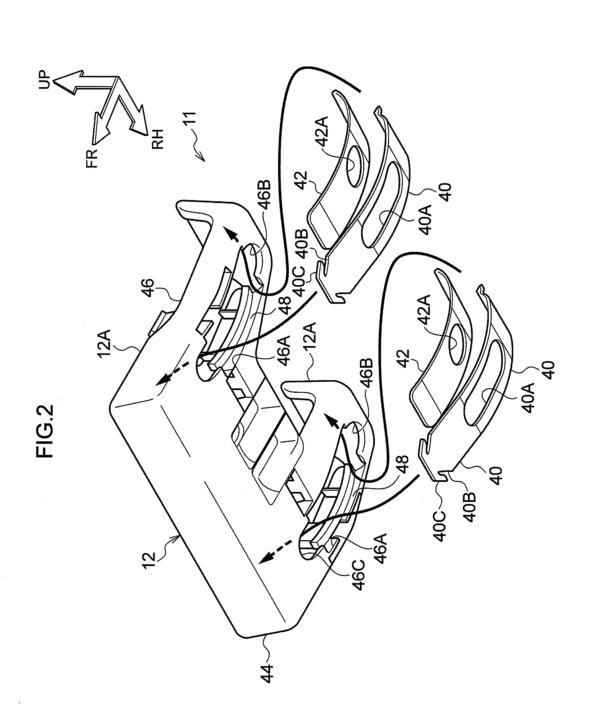
[0034]Headrest Device Configuration

[0035]As illustrated in FIG. 1, the headrest device 10 is provided above a seatback 100 that configures a vehicle seat, and is configured principally including a headrest 14 having a headrest structure 11, a headrest stay 16 and a headrest rotating structure 18.

[0036]The headrest 14 is configured principally including a headrest cushion portion 20 that forms a main body of the headrest 14, and a skin member 22 that covers the headrest cushion portion 20. The headrest cushion portion 20 is formed so as to cover the headrest rotating structure 18, and, from the s...


PUM


Abstract

A headrest structure and a headrest device, including a bottom plate provided at a lower face of a headrest, and provided with an elongated hole extending in a seat front-rear direction through which a stay is inserted, a guide sheet having the same width as that of the elongated hole, that is longer in length than the elongated hole, whose both end portions are slidably supported by the bottom plate, and that is provided with an elongated guide hole smaller than the elongated hole, a concealing sheet provided with an attachment hole to which the stay is attached, and that is overlapped slidably on an upper face of the guide sheet so as to cover the elongated guide hole, and a wall portion that is formed at the bottom plate, and that restricts movement of the guide sheet and the concealing sheet in a seat width direction, are provided.

Description

CROSS-REFERENCE TO RELATED APPLICATION[0001]This application claims priority under 35 USC 119 from Japanese Patent Application No. 2013-103543 filed May 15, 2013, the disclosure of which is incorporated by reference herein.BACKGROUND[0002]1. Field of the Invention[0003]The present invention relates to a headrest structure and a headrest device provided with the headrest structure.[0004]2. Related Art[0005]A headrest device is known in which an elongated hole is formed to a lower face of a headrest, a stay is inserted through the elongated hole, and the headrest is attached so as to be capable of rotating in a seat front-rear direction. In this kind of the headrest device, a closing plate covering the elongated hole is provided at the inside of the headrest, and by changing an angle of the closing plate interlockingly with the rotating of the headrest, a headrest device is provided that constantly closes off the elongated hole of the headrest (for example, Japanese Patent Application...

Claims


Application Information

Patent Timeline
IPC IPC(8): B60N2/48
CPCB60N2/48B60N2/4838B60N2/58B60N2/6009B60N2/838B60N2/847
Inventor SUNAGA, TOSHIAKIYAJIMA, TAKAHIRO
Owner NHK SPRING CO LTD
Why Eureka
Try Eureka