Surgical Microscope with Enlarged Working Distance

a surgical microscope and working distance technology, applied in the field of surgical microscopes, can solve the problems of increasing complexity, increasing cost, and unsatisfactory range of working distance achieved with common surgical microscopes, and achieve the effect of extending working distan

Active Publication Date: 2014-11-20
CARL ZEISS MEDITEC AG
View PDF3 Cites 4 Cited by
  • Summary
  • Abstract
  • Description
  • Claims
  • Application Information

AI Technical Summary

Benefits of technology

[0008]Embodiments are therefore directed to a surgical microscope enabling a variation of its working distance to a wide extent, and in particular a larger working distance as compared to common surgical microscopes.
[0018]The construction of the objective with two lens groups, with one of these lens groups consisting of at least three lenses and having a negative optical power altogether, enables to vary the working distance in a range that goes beyond the range typical for surgical microscopes.
[0032]According to an embodiment, the objective as a whole causes an imaging of an object disposable in the focal plane of the imaging system to infinity. This enables a modular structure of the surgical microscope.

Problems solved by technology

The simultaneous provision of an overview camera in addition to a surgical microscope increases complexity, since there are two different tools to be handled, and increases cost, since two different tools need to be procured and maintained.
Despite the larger working distance as compared to conventional reflected-light microscopes, the range of working distances achieved with common surgical microscopes is unsatisfactory.

Method used


Image

  • Surgical Microscope with Enlarged Working Distance
  • Surgical Microscope with Enlarged Working Distance
  • Surgical Microscope with Enlarged Working Distance

Examples


Embodiment Construction

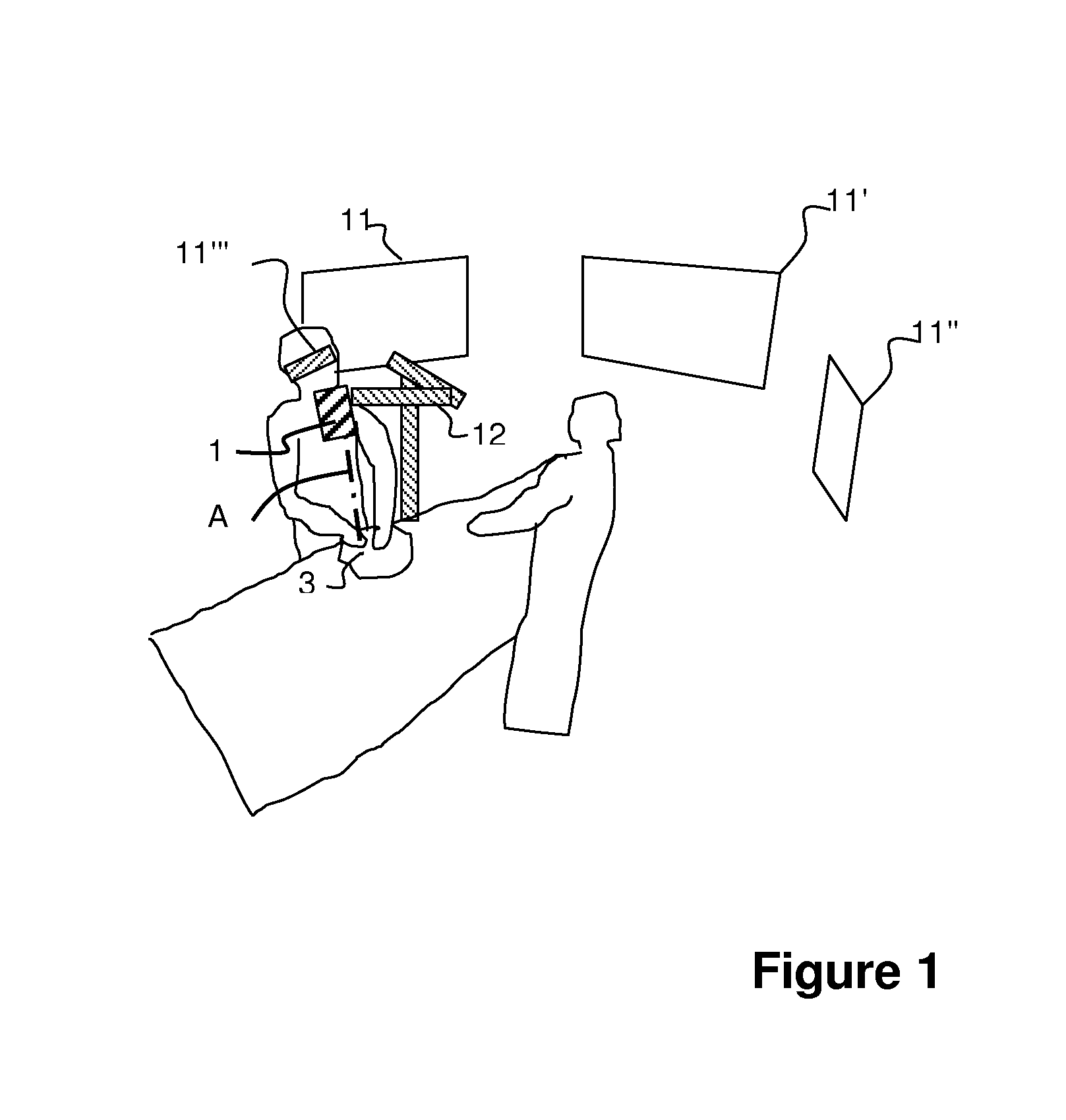
[0052]With reference to FIG. 1, a schematic representation of an exemplary use of a surgical microscope 1 according to an embodiment of the invention in a surgical procedure is shown.

[0053]The surgical microscope 1 is supported by a floor stand 12 moveable on rollers (not shown), and by using the stand, a user can move it manually such that an optical axis A of an objective (shown in FIG. 2) is directed onto an operation area 3 to be imaged. The magnified image of the operation area 3 generated by the surgical microscope 1 is output via lines (not shown) and three monitors 11, 11′, and 11″, as well as to a head-mounted display 11′″ of a user via a radio interface.

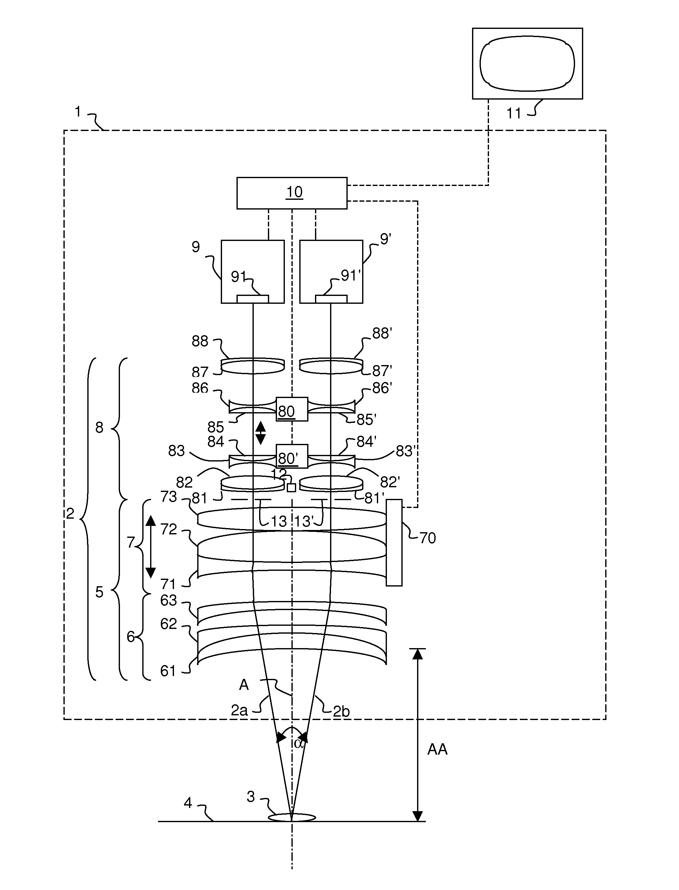
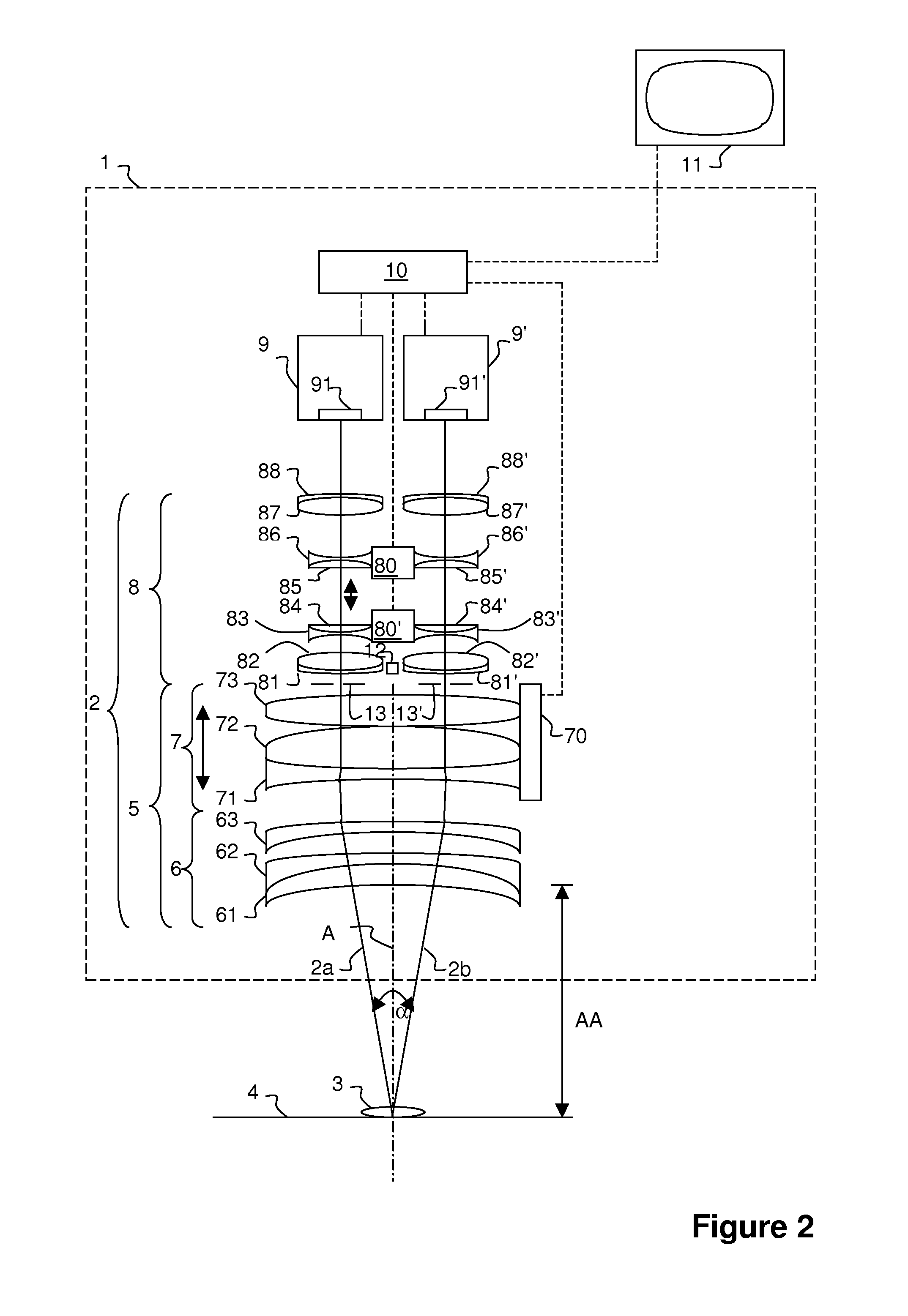
[0054]As schematically shown in FIG. 2, the surgical microscope 1 of FIG. 1 is a stereoscopic microscope having an imaging system 2 providing two optical imaging paths 2a, 2b intersecting in a focal plane 4 of the imaging system 2 of the surgical microscope 1 at a stereoscopic angle α. The value of the stereoscopic angle α ...


PUM


Abstract

A surgical microscope 1 comprises an imaging system 2 providing a magnified multidimensional image of an object 3 disposable in a focal plane 4 of the imaging system 2 along at least one optical imaging path 2a, 2b. The imaging system 2 comprises an objective 5 having at least two lens groups 6, 7, through which the at least one optical imaging path 2a, 2b passes consecutively, and which define the focal plane 4 of the imaging system 2. At least one lens group 6 of the objective is moveable along its optical axis relative to the at least one other lens group 7 of the objective. The objective's first lens group 6 located directly adjacent to the focal plane 4 along the at least one optical imaging path 2a, 2b consists of at least three optical lenses 61, 62, 63 and has altogether a negative optical power.

Description

CROSS-REFERENCES TO RELATED APPLICATIONS[0001]The present application claims priority of Patent Application No. 10 2013 008 090.8, filed May 10, 2013 in Germany, the entire contents of which are incorporated by reference herein.FIELD OF THE INVENTION[0002]The present invention relates to a surgical microscope (also referred to as operating microscope) adapted for enabling a variation of its working distance to a wide extent.BACKGROUND[0003]Surgical microscopes are optical reflected-light microscopes designed for use in medical surgery and providing a magnification typically in the range from 5×-30×. Compared to other optical reflected-light microscopes, surgical microscopes use an objective having an enlarged focal distance of typically between 175 mm and 550 mm and a correspondingly large working distance (distance between the lens vertex of the objective lens of a surgical microscope located closest to an object to be imaged and the object) of typically between 200 mm and 500 mm. ...

Claims


Application Information

Patent Timeline
Patent Type & Authority Applications(United States)
IPC IPC(8): G02B21/02G02B21/22G02B21/00
CPCG02B21/02G02B21/22G02B21/0012A61B90/20
Inventor HOEGELE, ARTUR
Owner CARL ZEISS MEDITEC AG
Why Eureka
Try Eureka