
Method of installing packing in a remote manufacturing yard

a manufacturing yard and packing technology, applied in the field of remote manufacturing yard packing installation, can solve the problems of increasing the cost of maintenance and additional problems, limiting the size of the asus, and increasing the cost of operation, so as to reduce the logistic effort and reduce the cost

Active Publication Date: 2014-11-27
LAIR LIQUIDE SA POUR LETUDE & LEXPLOITATION DES PROCEDES GEORGES CLAUDE
View PDF12 Cites 10 Cited by
  • Summary
  • Abstract
  • Description
  • Claims
  • Application Information

AI Technical Summary

Benefits of technology

The patent text describes a way to increase manufacturing flexibility and reactivity by allowing additional capacities to current manufacturing capacities. This is achieved by breaking down the level of structured packing into multiple sections and arranging the packing strips in a box in an alternating fashion to lower the packed height. The technical effect is a more flexible and efficient manufacturing process.

Problems solved by technology

As such, the roads, waterways, and bridge clearances create a practical limit on the sizes of the ASUs.
As such, the industry is facing a serious challenge in trying to meet these needs in a cost effective manner.
While this setup can provide the necessary flows, it creates additional problems related to maintenance and costs more than operating one ASU.
Areas that are landlocked and away from large navigable rivers also suffer from these aforementioned drawbacks.

Method used


Image

  • Method of installing packing in a remote manufacturing yard
  • Method of installing packing in a remote manufacturing yard
  • Method of installing packing in a remote manufacturing yard

Examples


Embodiment Construction

[0299]While the invention will be described in connection with several embodiments, it will be understood that it is not intended to limit the invention to those embodiments. On the contrary, it is intended to cover all the alternatives, modifications and equivalence as may be included within the spirit and scope of the invention defined by the appended claims.

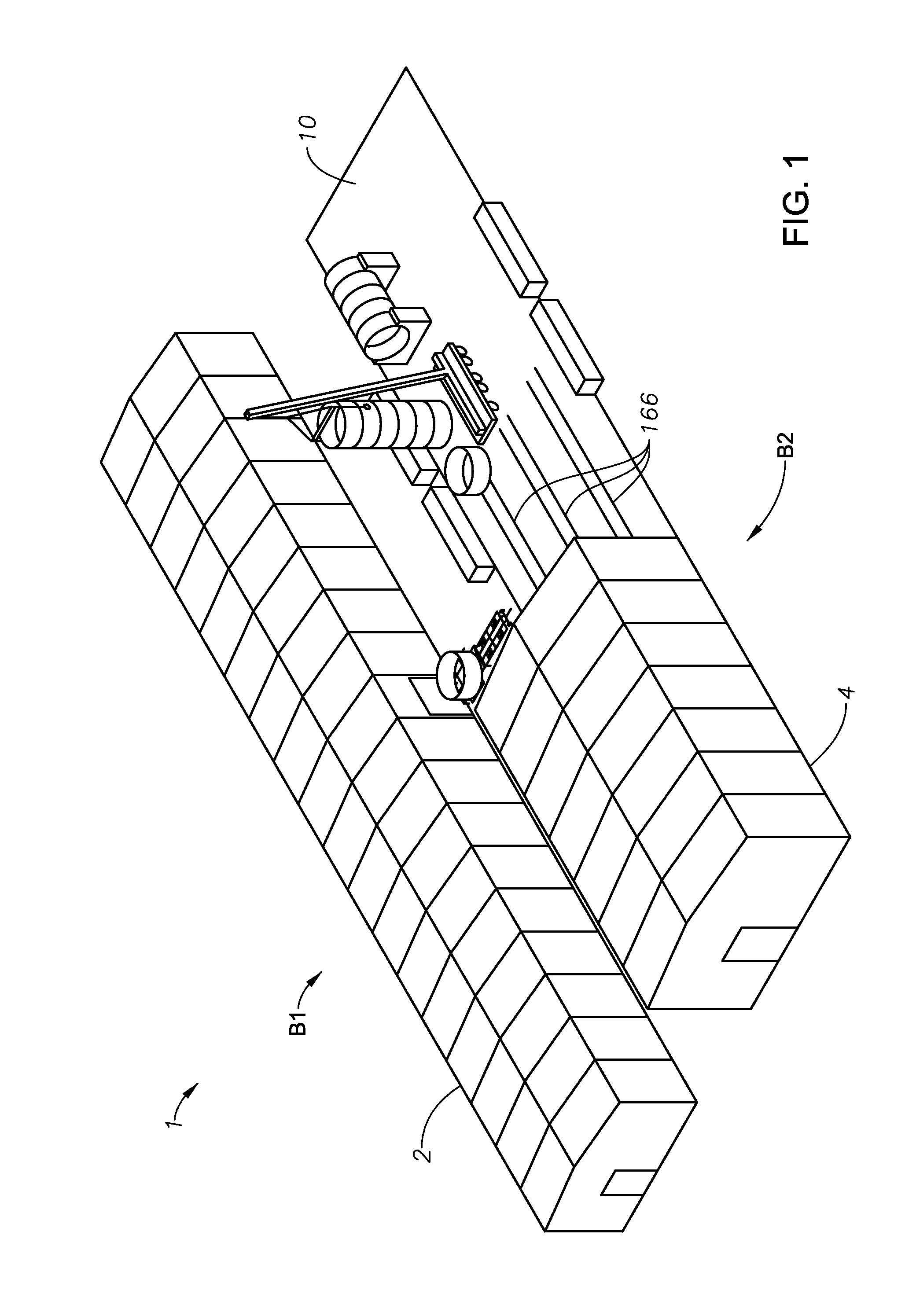
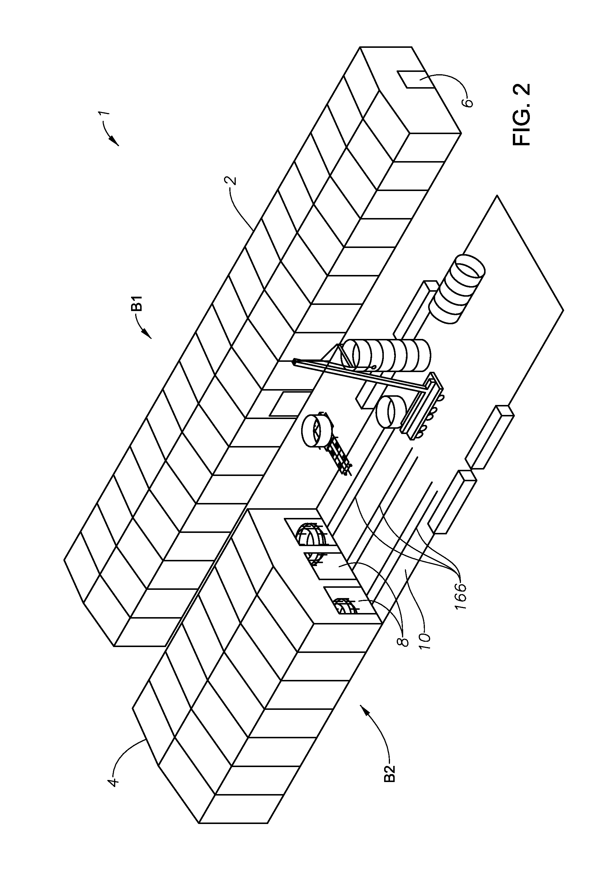
[0300]In certain embodiments, the primary drivers for determining which components of the ASU could be made remotely can include remote fabrication by inexperienced craft, the transport costs exposure and all the risks associated with manufacturing in a harsh environment.

[0301]In one embodiment, the method and device can be altered or tailored to an individual user's need. For example, the method can include identifying a user's requirements for land surface, building sizes, equipment / tooling and utilities which in turn will determine the design and construction requirements, percentage or ratio of the actual overall columns a...


PUM

PropertyMeasurementUnit
Lengthaaaaaaaaaa
Angleaaaaaaaaaa
Diameteraaaaaaaaaa

Abstract

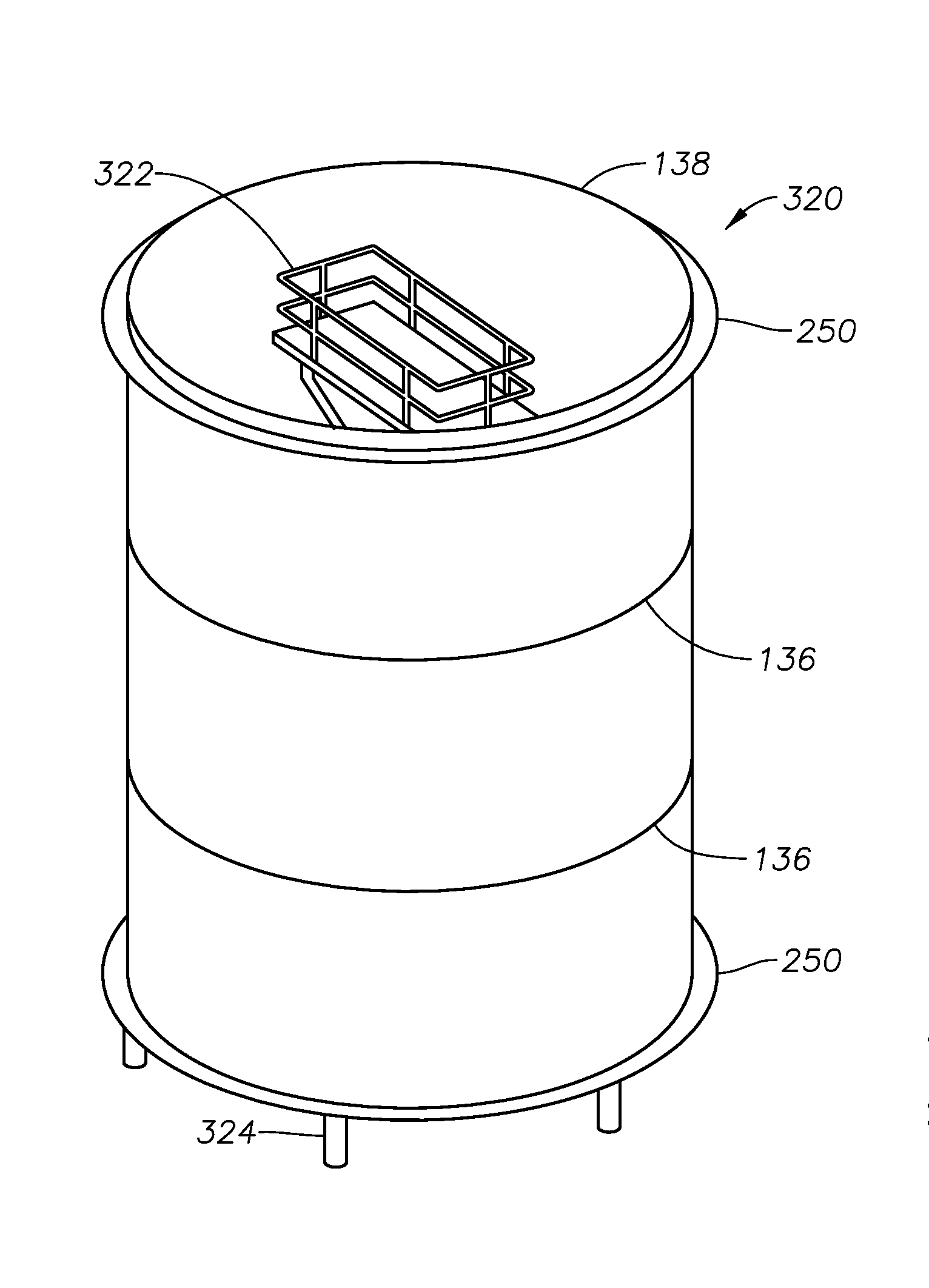
A method for installing packing in a remote manufacturing yard is provided. The method can include the steps of manufacturing structured packing in a facility away from the remote manufacturing yard; splitting a level of the structured packing into a plurality of sections and then placing each section into a separate box for transport, wherein each box can include an inner profile configured to match its section of packing so as to reduce damage to the packing during transport; transporting the boxes to the remote manufacturing yard; and installing the packing into a column section.

Description

RELATED APPLICATIONS[0001]This application claims priority to U.S. Provisional Application Ser. No. 61 / 827,096 filed on May 24, 2013; U.S. Provisional Application Ser. No. 61 / 827,103 filed May 24, 2013; and U.S. Provisional Application Ser. No. 61 / 921,164 filed Dec. 27, 2013, all of which are hereby incorporated by reference in their entireties.TECHNICAL FIELD OF THE INVENTION[0002]The present invention relates to a method used when building air separation units in a remote location using a mobile manufacturing yard.BACKGROUND OF THE INVENTION[0003]Air separation units (ASUs) are typically constructed in fabrication shops and then transported to their installation sites via roads and waterways. As such, the roads, waterways, and bridge clearances create a practical limit on the sizes of the ASUs. However, the market's need for ASUs has grown tremendously, with future projections rising even more. As such, the industry is facing a serious challenge in trying to meet these needs in a ...

Claims


Application Information

Patent Timeline
IPC IPC(8): B65B55/20B65B55/00B65B23/00
CPCB65B55/20B65B55/00B65B23/00B01J19/325E01B23/10E04G1/36E04G3/243E04G21/14E04G21/16E04G21/162E04G21/242E04H5/02B01J2219/32275E04G1/18E04H5/10F25J3/0489F25J2290/42B66C1/10E04G1/362E04G5/14E04G21/28E04G2005/125E04G1/15E04G5/061E04G21/142B23K9/0206B23K9/173B23K9/23B65B65/003E04G2021/248B01D3/00B01D3/28B01D3/32Y10T29/5137Y10T29/49631Y10T29/49817Y10T29/49998Y10T29/49826Y10T29/53974B23K2101/06B23K2103/02B21B39/04B21B39/16B21B39/34B66F5/04A47B37/00B65G67/02F25J3/04896E04H7/02F25J3/04472B21D5/12B21C37/0815B21D5/14B21C37/083B21B39/02E04H7/22E04H15/04E04H7/06B21D51/18F24F11/00B21B39/18
Inventor GRANGER, CLAUDE
Owner LAIR LIQUIDE SA POUR LETUDE & LEXPLOITATION DES PROCEDES GEORGES CLAUDE
Learn More