Continuous wall assemblies and methods

Active Publication Date: 2014-11-27
JOHNS MANVILLE CORP
View PDF19 Cites 22 Cited by
  • Summary
  • Abstract
  • Description
  • Claims
  • Application Information

AI Technical Summary

Benefits of technology

[0007]According to another embodiment, a method for insulating a structure is provided. The method includes coupling a plurality of structural support members (e.g., wall studs and the like) together to form a frame for a wall or ceiling. The method also includes coupling a plurality of insulative foam boards to the frame to form a continuous insulative wall or surface. The plurality of insulative foam boards are coupled to the frame via a plurality of fasteners having an elongate shaft that is insertable through a respective insulative foam board and into a respective structural support member to attach the respective insulative foam board to the respective structural support member. The fastener includes a cap that extends radially from the elongate shaft and that is positionable atop the respective insulative foam board to distribute an applied load relatively evenly about the insulative foam board. The method further includes applying a sealing tape across seams between adjacent insulative foam boards and over the cap, and/or applying a sealing caulk around insulative foam board penetrations, to seal the continuous insulative wall or surface such that the continuous insulative wall or surface forms an air barrier to restrict a passage of air through the wall to less than about 0.2 L/(s-m2) at a pressure of 75 Pa and to provide the exceptional structural integrity during extreme pressure loads.
[0008]According to another embodiment, an insulated structure is provided. The insulated structure includes a frame having a plurality of structural support members coupled together. The insulated structure also includes a plurality of insulative foam boards that are attached

Problems solved by technology

Without these products in conventional building techniques (e.g., the foam insulation materials), the air

Method used


Image

  • Continuous wall assemblies and methods
  • Continuous wall assemblies and methods
  • Continuous wall assemblies and methods

Examples


embodiment

Method Embodiment

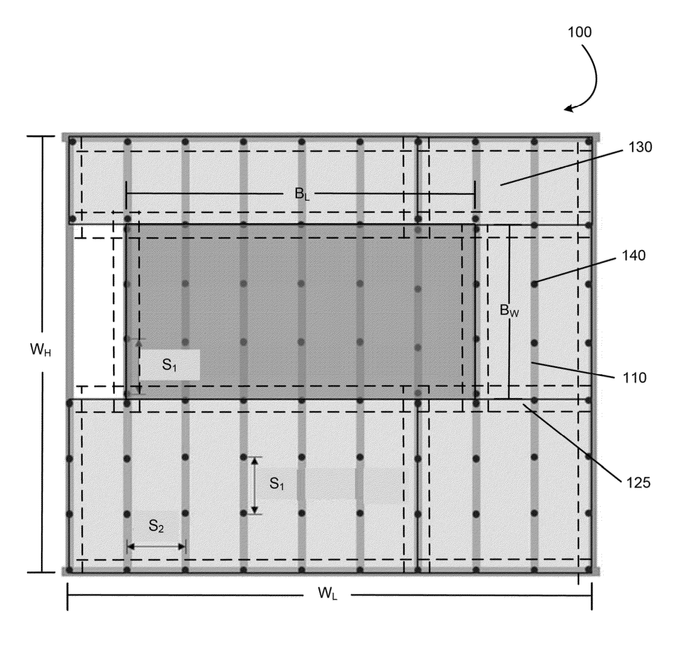
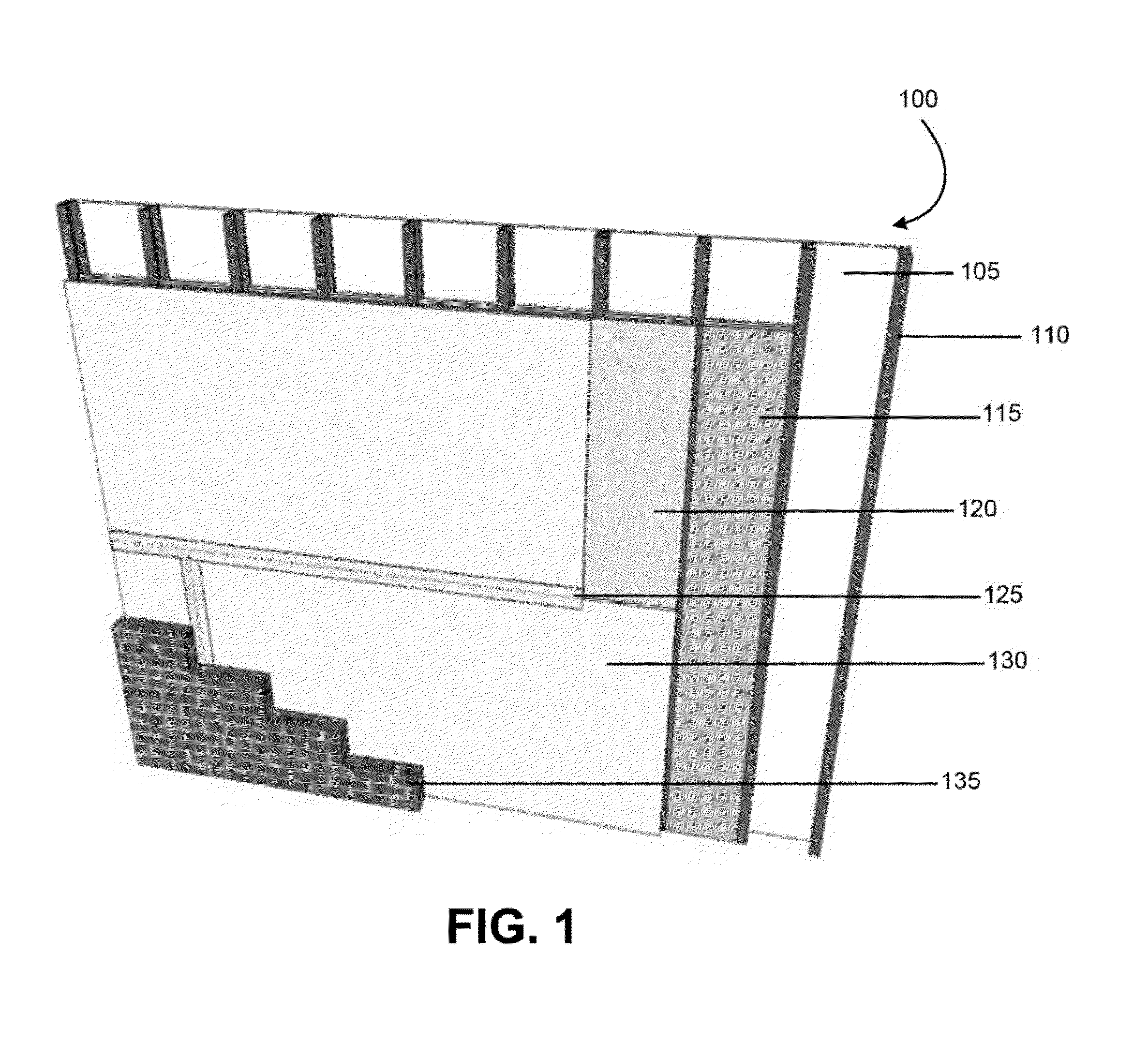
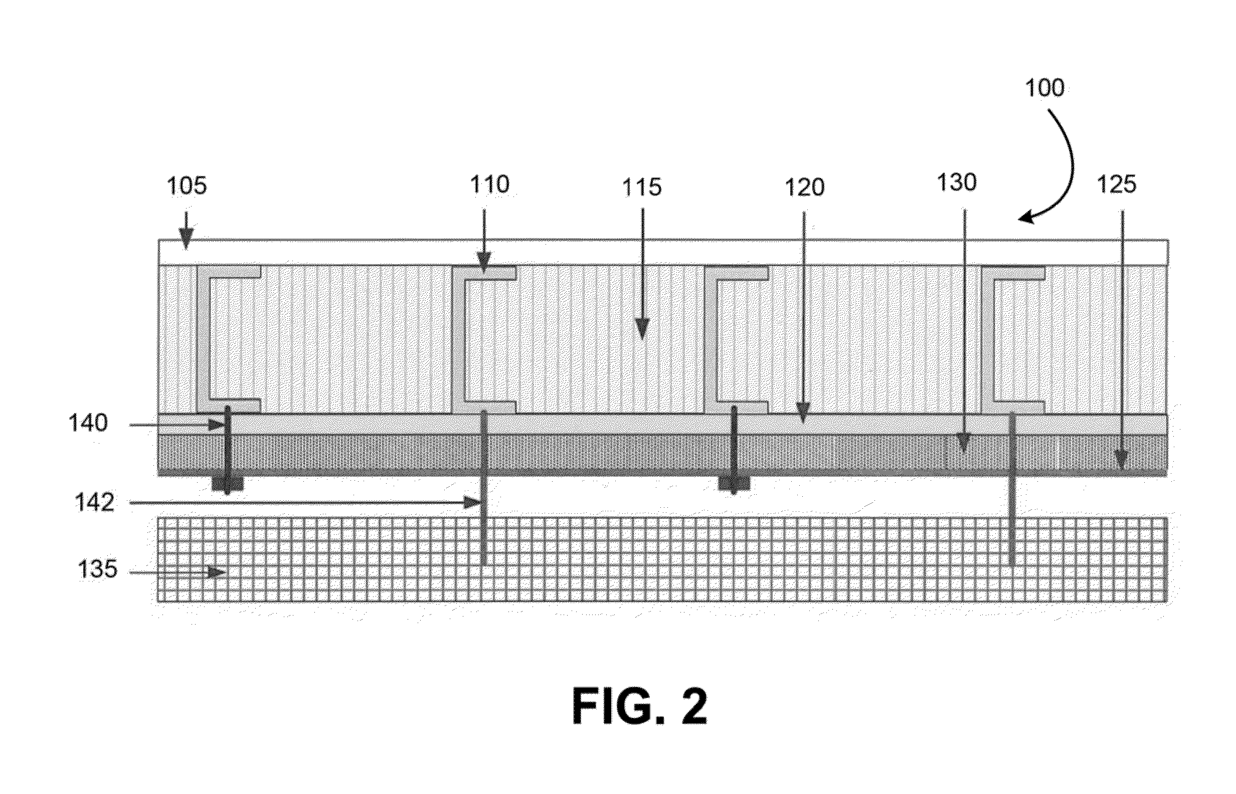
[0052]Referring now to FIG. 7, illustrated is a method 700 for providing a continuously insulated wall. At block 710, a frame is provided and, in some embodiments, exterior sheathing may be installed. The frame includes a plurality of structural support members (e.g., wall studs) that are attached or coupled together. At block 720, a plurality of insulative foam boards are coupled to the frame so as to form a continuous insulative wall or surface of the structure. The plurality of insulative foam boards are coupled to the frame via a plurality of fasteners that have an elongate shaft portion that penetrates through a respective insulative foam board and into a respective structural support member to attach the respective insulative foam board to the respective structural support member.

[0053]The fastener including a cap portion having a 2 inch diameter. The cap portion is positioned atop the respective insulative foam board when the fastener is inserted through the ...


PUM


Abstract

According to one embodiment, an insulated structure includes a frame comprising a plurality of wall studs coupled together and a plurality of foam boards attached to the frame to form a continuous insulative wall. A plurality of fasteners attaches the foam boards to the frame. Each fastener includes an elongate shaft and a cap. The elongate shaft is configured to penetrate through a foam board and into a wall stud to couple the components together. The cap is configured to be positioned atop a foam board to distribute a load relatively evenly to the foam board. A sealing tape is applied across seams between adjacent foam boards and over the fasteners' caps to seal the wall. A sealing caulk is applied to secondary fasteners and penetrations to seal the wall. In some embodiments, the structure has a fastener density of about 1 fastener per 243 in2 of foam board.

Description

BACKGROUND OF THE INVENTION[0001]Construction of modern buildings constantly focus on manners of increasing energy efficiency in order decrease energy consumption while providing comfort to occupants. To increase a building's thermal efficiency, insulation is often applied to the outer and / or inner surfaces of the building. To further increase the thermal efficiency, air barriers are often created to minimize the flow of air between the surrounding environment and the building's interior. One construction technique for providing an air barrier is by building a continuous insulation wall assembly. Such wall assemblies are required under the 2012 International Energy Conservation Code, which has been adopted by five States.[0002]In conventional continuous insulation wall assembly building techniques, sealants are often used to produce the desired air barrier. For example, foam insulation materials are often applied between wall studs to seal seams or cracks between adjacent cover boar...

Claims


Application Information

Patent Timeline
IPC IPC(8): E04B2/00
CPCE04C2/46E04B1/7629E04F13/007E04F13/0833E04F13/142F16B15/02E04B1/762E04B1/7633E04B1/7637E04B1/388E04B1/66E04B1/80E04B2/02E04B2/30E04B2/56E04B2002/0202E04B2002/0243E04B2002/565E04B1/4171E04B2/562E04B2002/0245E04F13/14
Inventor MIKS, KATHRYN FINKFAY, RALPH MICHAELCALZAVARA, THOMAS S.BABINEAU, JR., FRANCIS JOHN
Owner JOHNS MANVILLE CORP
Why Eureka
Try Eureka