
Hose burst suppression sleeve system

a hose and sleeve technology, applied in the direction of pipe protection against damage/wear, mechanical equipment, manufacturing tools, etc., can solve the problems of hose bursts and/or leaks, exposing personnel to unsafe conditions, and affecting the safety of personnel or equipment, so as to improve the safety of personnel and the environment.

Inactive Publication Date: 2014-11-27
THE GATES CORP
View PDF6 Cites 6 Cited by
  • Summary
  • Abstract
  • Description
  • Claims
  • Application Information

AI Technical Summary

Benefits of technology

This patent is about a system that helps make hydraulic hoses safer and more efficient. It includes a special expansion coil and protective blanket that can prevent ruptures and leaks in the hose. The system can handle high pressure and can be applied to existing hose assemblies. This invention helps to make hydraulic hoses safer and more durable.

Problems solved by technology

Hoses are failed or taken out of service if they are not able to hold pressure for the amount of time specified by the manufacturer.
Current practices include laying pressurized hose on the ground for extended periods of time, which may expose personnel to unsafe conditions.
Hose bursts and / or leaks may be dangerous to personnel or equipment.
The test fluids and / or wash fluids may be environmentally hazardous.

Method used


Image

  • Hose burst suppression sleeve system
  • Hose burst suppression sleeve system
  • Hose burst suppression sleeve system

Examples


first embodiment

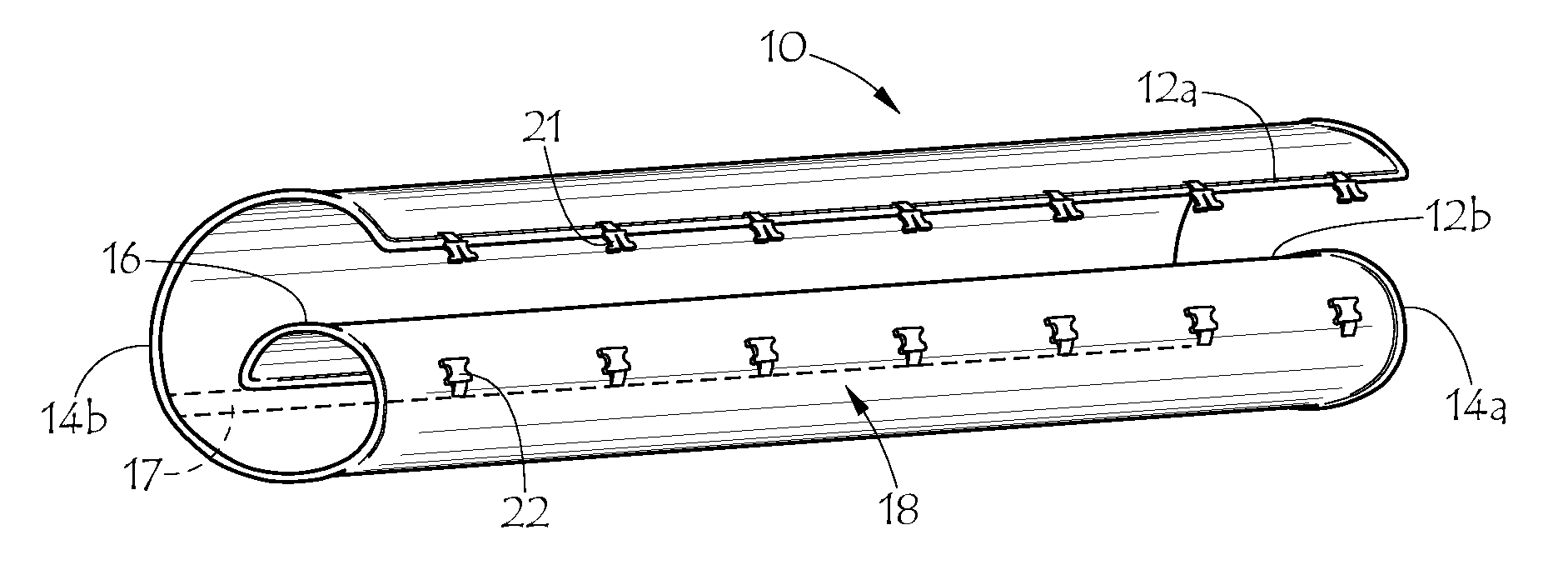
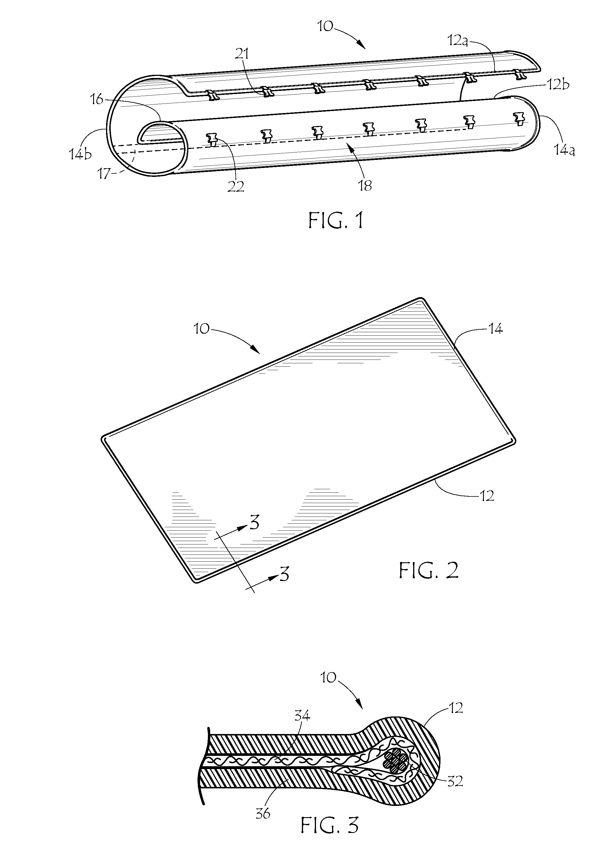
[0024]FIG. 1 shows the inventive fluid suppression blanket. In FIG. 1, fluid suppression blanket 10 is in the form of a rectangular sheet partially coiled in the longitudinal direction. Blanket 10 has two longitudinal edges 12a and 12b, and two end edges, or ends 14a and 14b. Blanket 10 is adapted to coil around a hose or other tubular object in a tubular or cylindrical form, and is adapted so one edge 12a overlaps the other edge 12b, defining an overlap portion 16 of overlap distance 17. Blanket 10 includes longitudinal edge fastener system 18. The edge fastener system may be comprised of buckles, hooks, loops and eyes, ties, chains and locks or other fastening mechanisms or systems. Edge fastener system 18 as shown comprises a number of buckles with male buckle portions 21 and female buckle portions 22. FIG. 2 shows containment blanket 10 in a flat configuration. At least one edge of ends 14 and edges 12 may be reinforced. All peripheral edges 14 and 12 of the blanket may be reinf...

second embodiment

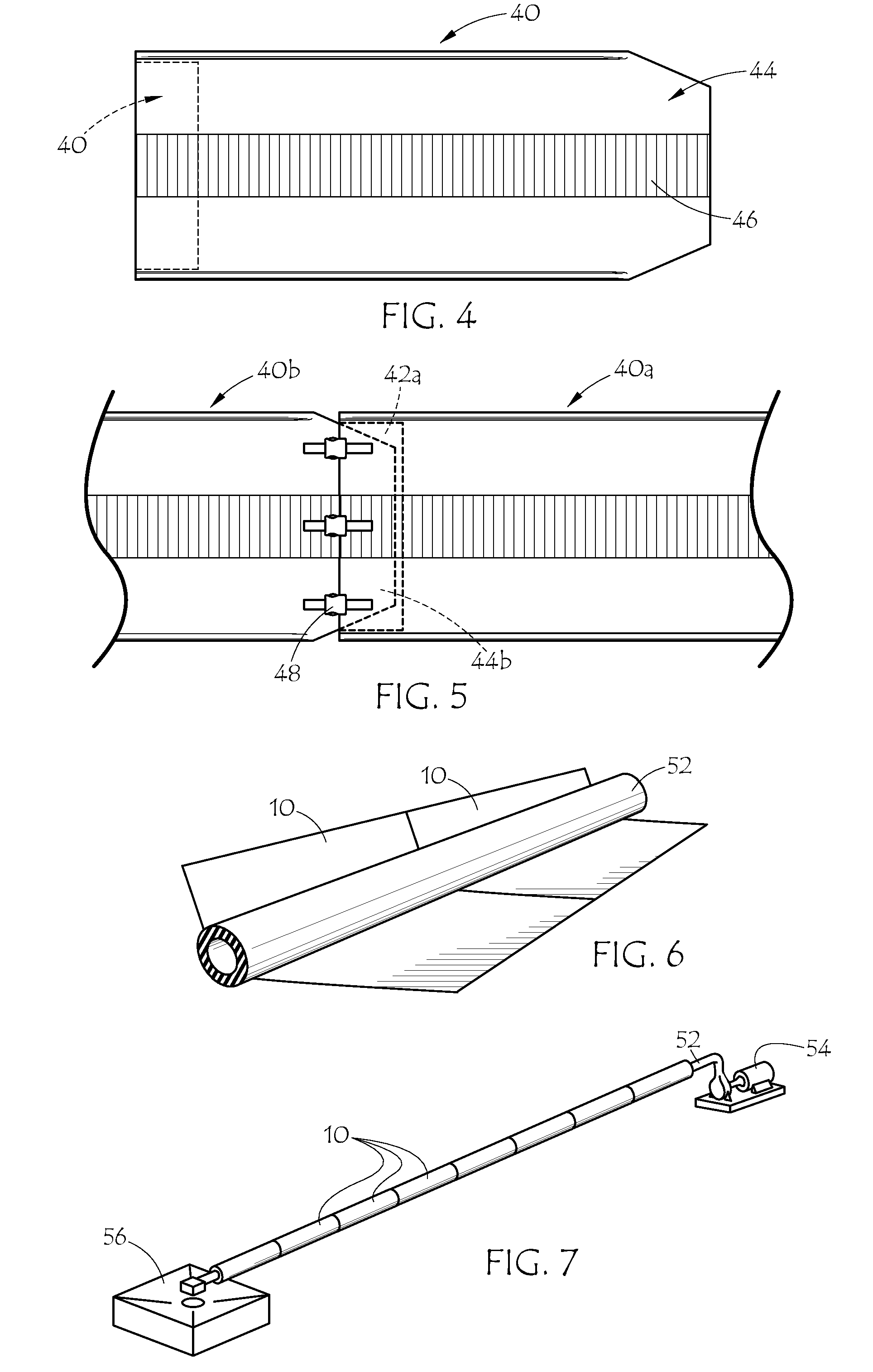
[0030]FIG. 8 illustrates the inventive blankets 80a and 80b, showing a partially fragmented cross section of blanket 80a having multiple, loose layers of sheet materials, including impervious outer and inner cover layers and internal reinforcing fabric layers. In FIG. 8, there are two impervious layers, outer cover layer 82 and inner cover layer 84, along with a number of pervious layers of fabric 86 sandwiched in between. Buckles 88 are attached to reinforcing webbings 87 which then encircle the coiled blanket completely, increasing the hoop strength of the blanket. Similar buckles 89 are used to join blankets end-to-end. Pervious layers 86 may help to contain fluid that happens to penetrate an impervious layer. Edge-cord reinforcement 32 is present on the two long edges of each blanket. Webbings 87 are fastened to outer layer 82 only. In other words, the webbings are not stitched in a way that anchors the fabric layers 86 to the outer layer 82 or to the inner layer 84. The interna...


PUM

PropertyMeasurementUnit
diameteraaaaaaaaaa
diameteraaaaaaaaaa
pressuresaaaaaaaaaa

Abstract

A protective suppression system including one or more sleeves of expansion coil of energy-absorbing material wrapped around a hose and a blanket which can be wrapped loosely around the wrapped hose. The longitudinal edges of the blanket fasten together to form a protective cylindrical tube, and can be joined end-to-end with one or more additional blankets to extend the protective tube to a desired total length. The system thus can provide improved safety to personnel and the environment by shielding a hose under pressure to suppress bursts, block leaks and by redirecting or channeling test fluids and cleaning fluids.

Description

CROSS REFERENCE TO RELATED APPLICATIONS[0001]This application is a continuation-in-part of international application number PCT / US2013 / 072266 filed Nov. 27, 2013, which claims priority from U.S. Provisional Application No. 61 / 740,734 filed Dec. 21, 2012, the entire contents of each of which are hereby incorporated herein by reference.BACKGROUND OF THE INVENTION[0002]1. Field of the Invention[0003]This invention relates generally to a protective blanket system used to shield and suppress fluid leaks from a hose under high internal pressure, more particularly to a system with a blanket that can be coiled loosely around a helically-wrapped hose and secured in a tubular shape and wherein multiple blankets can be joined end-to-end.[0004]2. Description of the Prior Art[0005]In recent years, improved safety practices in the oil and gas industry have required oil rig operators to recertify critical equipment. There are now industry guidelines from organizations like ‘Oil and Gas UK’ which c...

Claims


Application Information

Patent Timeline
Patent Type & Authority Applications(United States)
IPC IPC(8): F16L11/10
CPCF16L11/10F16L57/00F16L57/06Y10T29/49826
Inventor HILL, JAY RICKMCKINLEY, JONATHAN JAMESGRAY, YELENAHILLS, ANDYHENDERSON, KIMSWIFT, JONATHAN CLARK
Owner THE GATES CORP
Learn More