
Medallion Fan

a ceiling fan and blade technology, applied in the direction of machines/engines, mechanical equipment, liquid fuel engines, etc., can solve the problems of bladed ceiling fans causing flickering shadows, increasing the need for ceiling fans, and increasing the cost of air conditioning and heating

Active Publication Date: 2014-11-27
HUNTER FAN
View PDF7 Cites 18 Cited by
  • Summary
  • Abstract
  • Description
  • Claims
  • Application Information

AI Technical Summary

Benefits of technology

This patent is for a new kind of fan that can be installed in a ceiling. It is designed to be quieter, more attractive, and more energy-efficient than traditional ceiling fans. It can be used in a space that needs to be cooled or has lots of dust. It can also be used to adjust the humidity and can even help to filter out harmful particles from the air. The fan is designed to blend into the architecture of the space, making it a seamless addition. Additionally, it can also be used to mount other fixtures, like lighting, and can be equipped with various technology to improve its performance.

Problems solved by technology

The popularity or even necessity of ceiling fans has grown steadily with the cost of air conditioning and heating.
For example, bladed ceiling fans will cause flickering shadows if light passes through the rotating blades and flickering reflections in eyeglasses.
These can cause headaches in people who are trying to focus their vision as in reading or doing close work such as hand assembly.
It also believed that such flickering light could possibly trigger an epileptic seizure in some individuals.
Bladed fans by nature of their design cause a pulsating air flow that some people find objectionable.
Low ceilings present a problem, even to those considering a close mounted fan, because the rotating blades pass too close to the occupant's heads.
When such a fan is mounted over a dining table, food is cooled too quickly.
As a result, existing fans are often replaced with such a fixture during remodeling.
However, accumulated particulate in said rotating filters effects balance, causing the rotating assembly to wobble.
A static electrical charge will collect on the blades of most fans, which will cause an accumulation of said particulate on these blades.

Method used


Image

  • Medallion Fan
  • Medallion Fan
  • Medallion Fan

Examples


Embodiment Construction

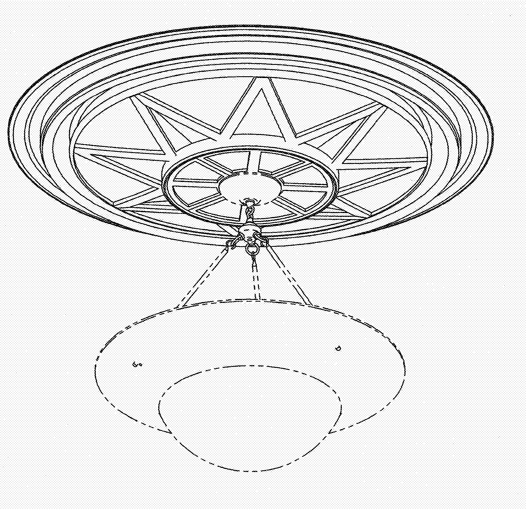
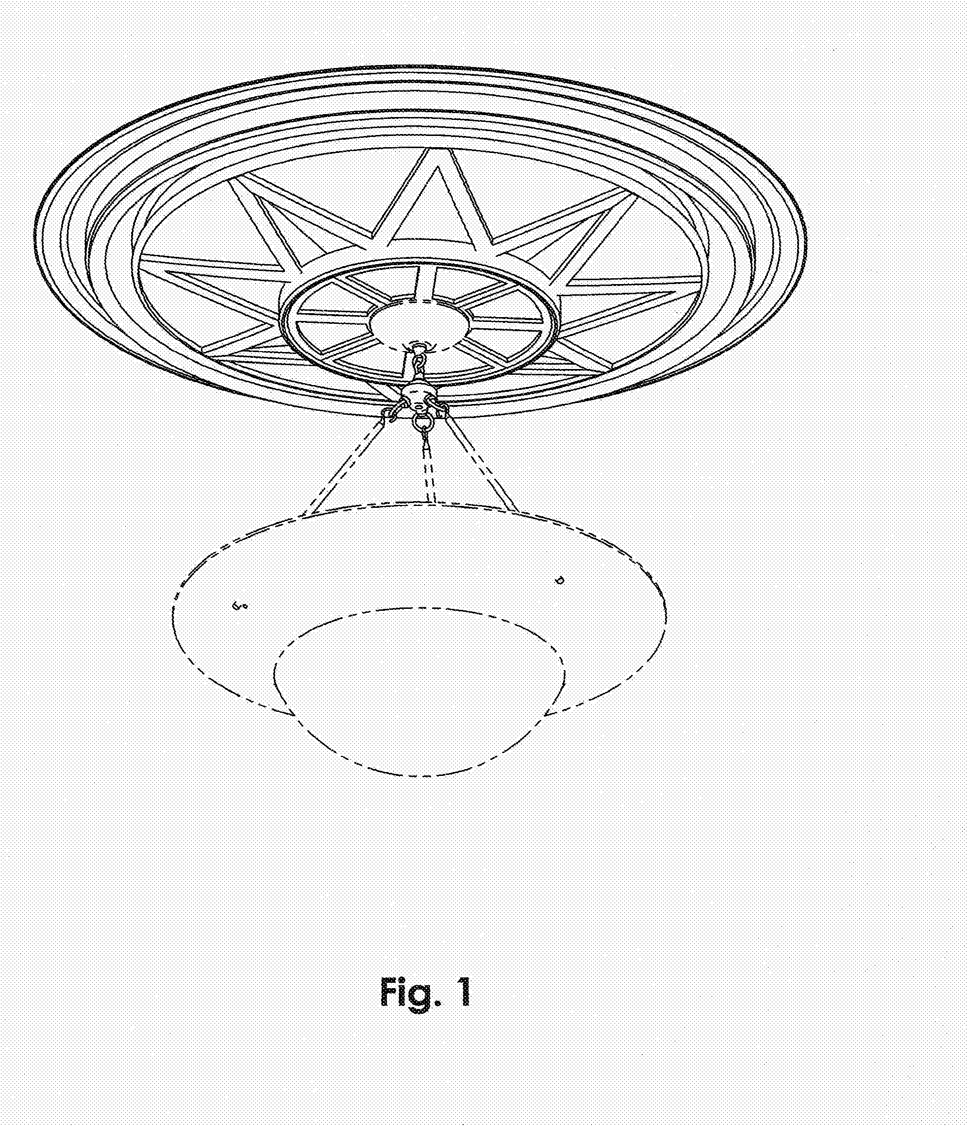
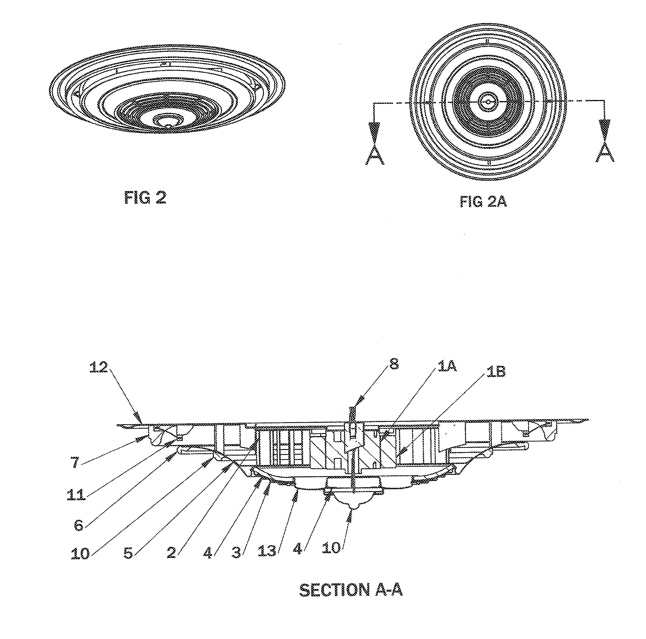
[0040]According to a broad aspect of the present invention there is provided an air circulating device comprising a ceiling plate to which is mounted a motor the driven, portion of which drives an impeller; an enclosure which is comprised of all or some of the following: impeller shroud; internal airflow channeling means; primary air inlet; airflow discharge outlet and means to direct the airflow in the direction intended. All of the forgoing is intended to blend into the architectural style of a space in a manner similar to a ceiling medallion.

[0041]It is within the scope of the invention that said enclosure may be generally circular, rectangular or polygonal and may have decorative embellishment about the perimeter and on the downward facing surfaces.

[0042]In the simplest embodiment, the enclosure and ceiling plate are mounted to the ceiling, proximate to an electrical supply run within the ceiling and rigidly to a ceiling supporting frame member. Additional toggle bolts or simila...


PUM


Abstract

This invention relates to a ceiling mounted air circulating apparatus comprising, in combination: a motor; an essentially centrally located radial or axial air impeller; air guiding means; optional airflow enhancement by means of air amplification means; an optional centrally located wiring path from an electrical power source to a wiring enclosure suitable for hanging a lighting fixture or chandelier; and decorative embellishments, all of which are arranged to blend with the architectural style of a space in a manner similar to a decorative ceiling medallion, the planform of which, when viewed from below may be circular, rectangular, or polygonal. Optionally, the apparatus of the present invention may embody any of the following; heating, cooling, filtration means, positive ion generation means, and / or air sterilization means.

Description

REFERENCE[0001]This application encompasses, extends and continues Provisional Application 61 / 652,242 filed on May 8, 2012FIELD OF THE INVENTION[0002]This relates to the field of Ceiling Mounted Fans used to circulate air to provide convective cooling of the occupants of a space and to provide better temperature distribution during heating season and to a lesser extent, the general field of heating, ventilating and air conditioning.BACKGROUND OF THE INVENTION[0003]The common bladed ceiling fan was invented in 1887 by Philip Diehl. Over the years, many improvements in function were made and there have been many variations in style, but the general form of a motor suspended from the ceiling, directly or at the end of a downrod, driving a plurality of pitched blades commonly referred to as paddles has remained the same.[0004]For a discussion of existing ceiling fans of this type see, for example, Pearce, U.S. Design Pat. 297,456 issued Aug. 30, 1988; Gajewski, U.S. Pat. No. 7,481,626 B...

Claims


Application Information

Patent Timeline
Patent Type & Authority Applications(United States)
IPC IPC(8): F04D19/00
CPCF04D19/002F04D25/088F04D29/282F04D29/703F05D2270/173F04D17/16F04F5/16F04F5/46F04D29/441
Inventor CUNNANE, JEFFREY BUTLER
Owner HUNTER FAN
Learn More