Endoscope and endoscope system including same

Inactive Publication Date: 2014-11-27
PANASONIC INTELLECTUAL PROPERTY MANAGEMENT CO LTD
View PDF7 Cites 33 Cited by
  • Summary
  • Abstract
  • Description
  • Claims
  • Application Information

AI Technical Summary

Benefits of technology

[0010]According to the present invention, by changing the inclination angle of the optical axis of the first imaging unit, the image capturing area of the first imaging unit can be moved along the direction in which the two imaging units are arranged such that, even when t

Problems solved by technology

However, when the endoscope is moved and a distance to the object from each imaging unit is varied, the positional relationship between the image capturing areas of the two imaging units is changed, and thus, regions of the object in the two images become inconsisten

Method used


Image

  • Endoscope and endoscope system including same
  • Endoscope and endoscope system including same
  • Endoscope and endoscope system including same

Examples


Example

First Embodiment

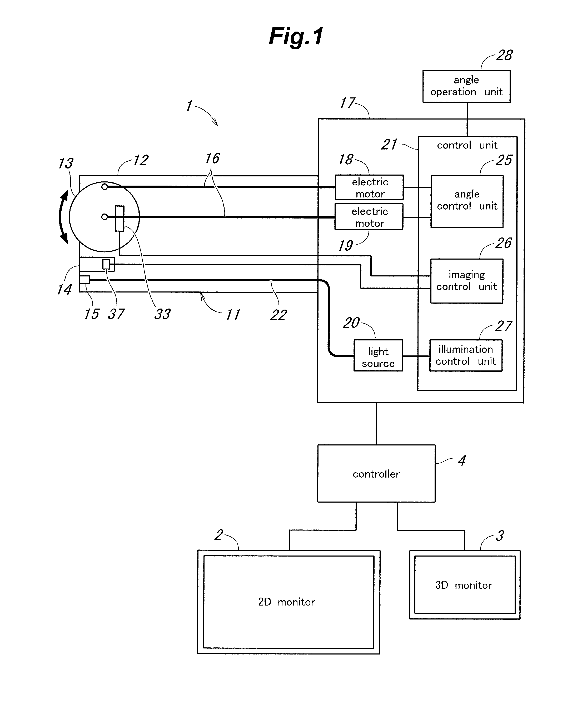
[0044]FIG. 1 is an overall configuration diagram showing an endoscope system according to the first embodiment. The endoscope system includes an endoscope 1 to be inserted into a human body (a subject to be observed) to take an image of an object such as an internal organ in the body, a 2D monitor (a first display device) 2 for displaying an image in two dimensions, a 3D monitor (a second display device) 3 for displaying an image in three dimensions and a controller (a display control device) 4 for controlling display of images on the 2D monitor 2 and the 3D monitor 3.

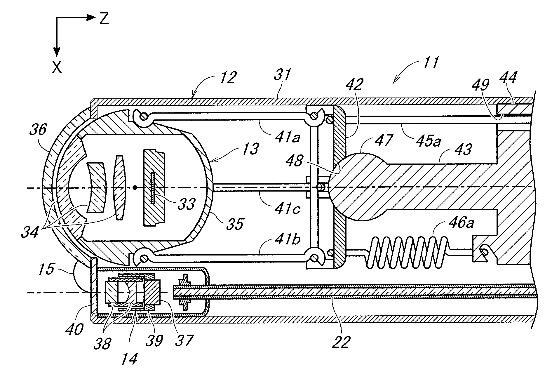
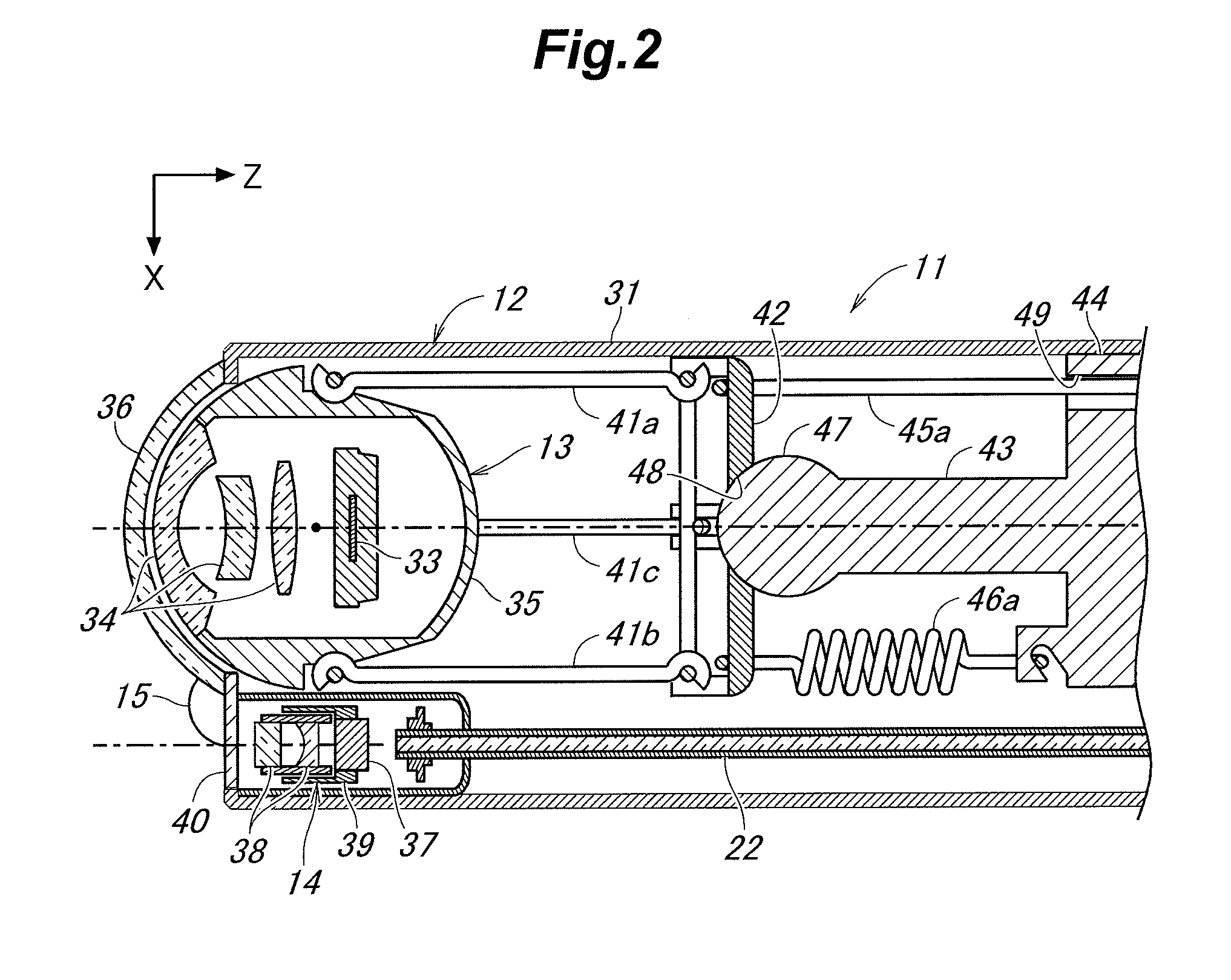
[0045]The endoscope 1 is what is called a rigid endoscope and its insertion portion 11 to be inserted into a body is not bendable. In a distal end portion 12 of the insertion portion 11 are provided side by side a first imaging unit 13 and a second imaging unit 14 for taking an image of the object. The first imaging unit 13 is provided such that an inclination angle of the optical axis thereof can be ch...

Example

Second Embodiment

[0102]FIG. 10 is a block diagram showing the imaging control unit 26 in an endoscope according to the second embodiment. It is to be noted that the second embodiment is similar to the first embodiment except for the points noted in the following.

[0103]In this second embodiment, the control unit 21 performs control to automatically adjust the inclination angle of the optical axis of the first imaging unit 13 such that the second image capturing area is maintained at a predetermined location in the first image capturing area irrespective of the object distance. The imaging control unit 26 includes an imaging position correcting unit 81 which corrects a displacement (positional mismatch) of the image capturing area of the first imaging unit 13 with respect to the image capturing area of the second imaging unit 14, whereby an operation to adjust the position of each of the image capturing areas of the imaging units 13, 14 becomes unnecessary, and thus, usability is impr...

Example

Third Embodiment

[0116]FIG. 13 is a perspective view showing a principal part of an endoscope according to the third embodiment. It is to be noted that the third embodiment is similar to the first embodiment except for the points noted in the following description.

[0117]In this third embodiment, a distal end portion 92 including a first imaging unit 13 and a second imaging unit 14 is provided to an insertion portion 91 via a bending portion 93 such that the distal end portion 92 is configured to change a direction thereof (i.e., head swinging motion). By changing the direction of the distal end portion 92 while the insertion portion 91 is inserted into an interior of the subject to be observed, it is possible to change the directions of the two imaging units 13, 14 simultaneously and to thereby observe a surgical site such as a tumor site from various directions.

[0118]In this third embodiment, similarly to the first embodiment, the endoscope may be configured to have an angle adjustm...


PUM


Abstract

An endoscope includes an insertion portion to be inserted into a subject to be observed, a first imaging unit and a second imaging unit arranged side by side in a distal end portion of the insertion portion, and a control unit which generates a 3D image from captured images taken by the first imaging unit and the second imaging unit. An optical axis of the first imaging unit can be changed to enable an image capturing area of the first imaging unit to be moved along a direction in which the first imaging unit and the second imaging unit are arranged. The endoscope includes an angle operation unit to change the inclination angle of the optical axis of the first imaging unit and an angle adjustment mechanism which changes the inclination angle of the optical axis of the first imaging unit according to an operation of the angle operation unit.

Description

TECHNICAL FIELD[0001]The present invention relates to an endoscope for taking an image of an interior of a subject to be observed which cannot be observed directly from outside, and an endoscope system including the endoscope, and particularly relates to an endoscope adapted to provide three-dimensional (3D) display as well as ordinary two-dimensional (2D) display and an endoscope system including the endoscope.BACKGROUND ART[0002]Endoscopes are widely used in order to observe an internal organ, etc. of a person during an operation or an inspection in medical treatment. Some of such endoscopes are configured such that an imaging unit is provided at a distal end portion of an insertion portion to be inserted into a human body and an image taken by this imaging unit is displayed on a monitor. If two imaging units are provided and a 3D monitor is used to display an image in three dimensions, the efficiency of the operation or inspection can be improved because an object such as an orga...

Claims


Application Information

Patent Timeline
IPC IPC(8): A61B1/00A61B1/05
CPCA61B1/05A61B1/00009A61B1/00183G02B23/2423G02B23/2469G02B23/2476A61B1/00096G02B23/2415A61B1/00188A61B1/00193A61B1/00194
Inventor TANAKA, SHOGOKOHNO, HARUHIKO
Owner PANASONIC INTELLECTUAL PROPERTY MANAGEMENT CO LTD
Why Eureka
Try Eureka