

Light source apparatus, method for adjusting the same and method for producing the same
a technology of light source apparatus and method, applied in the direction of mountings, telescopes, instruments, etc., can solve the problems of no methods that can solve all, and achieve the effects of low part count, easy optical axis adjustment, and maintaining positional relationship
- Summary
- Abstract
- Description
- Claims
- Application Information
AI Technical Summary
Benefits of technology
Problems solved by technology
Method used
Image

Examples
embodiment 1
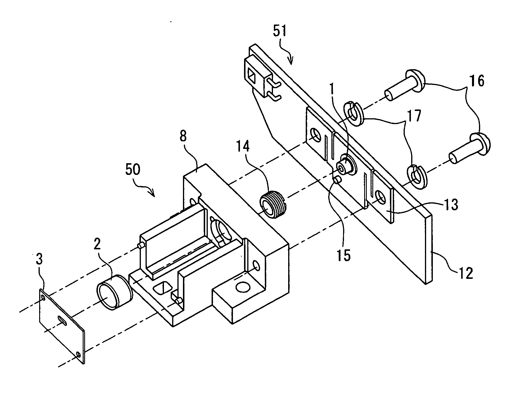
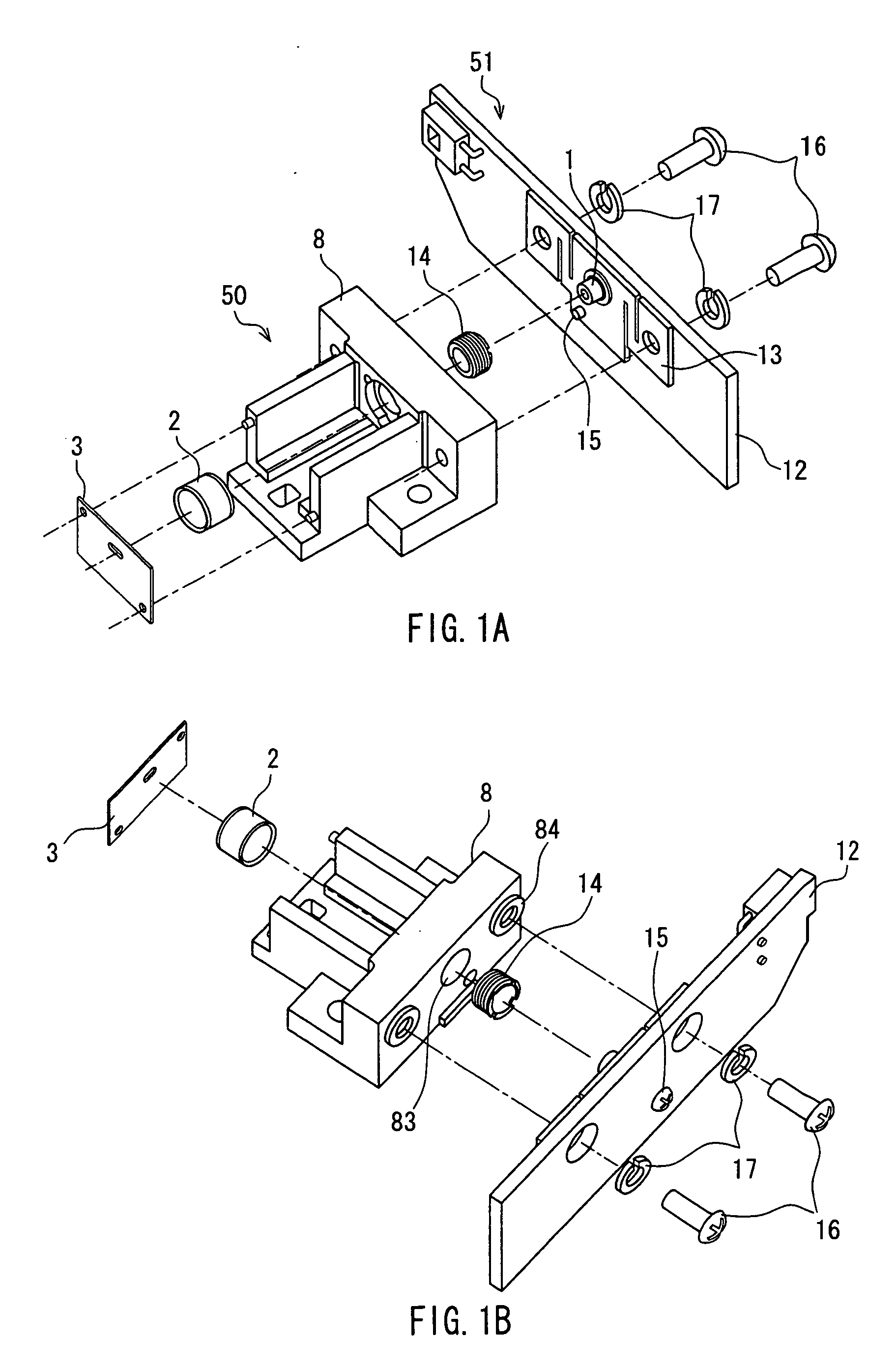
[0128]FIGS. 1A and 1B show exploded perspective views of a light source apparatus according to Embodiment 1 of the present invention. FIG. 1A is a perspective view, as viewed obliquely from the front, and FIG. 1B is a perspective view, as viewed obliquely from the back. The light source apparatus shown in FIGS. 1A and 1B is provided with a collimating lens unit 50 and a light source unit 51. The collimating lens unit 50 is provided with a collimating lens base 8, a collimating lens 2, a diaphragm 3 and an adjusting screw 14. The light source unit 51 is configured by fastening a light source supporting plate 13, to which a light source 1 is fixed, to a circuit board 12 with a fixing screw 15. The collimating lens unit 50 and the light source unit 51 are fastened with fixing screws 16.
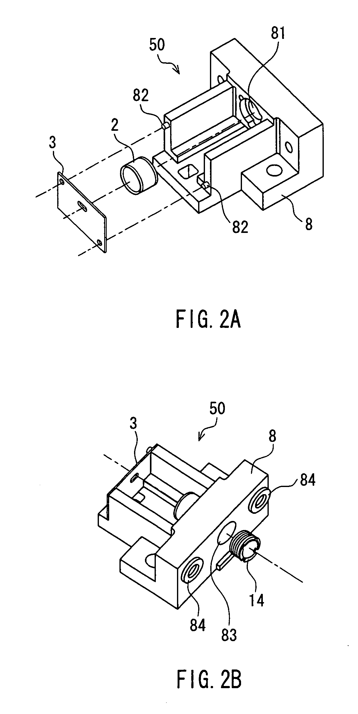
[0129] The detailed structure of this light source apparatus is described below, while explaining its assembly procedure. FIGS. 2A and 2B are perspective views illustrating the assembly of the collimati...
embodiment 2
[0232]FIG. 18A shows a cross-sectional view showing the configuration of a modification of Embodiment 1 in a simplified manner. FIG. 18B is an enlarged view showing a portion near the projection 21 (A portion) in FIG. 18A. The basic configuration of a light source apparatus according to this embodiment is the same as that of the light source apparatus described in Embodiment 1, and therefore only different parts are described. In the light source apparatus of this embodiment, two projections 21 for fixing the laser driving circuit are formed in the light source supporting plate 13, and engaging holes 22 corresponding to the projections 21 are formed in the circuit board 12.
[0233] The operations of assembly and adjustment of the light source apparatus in this embodiment are the same as those in Embodiment 1. In FIGS. 18A, a horizontal synchronization detecting light sensor 25 is mounted to the end of the circuit board 12. Because the vibration of the horizontal synchronization detec...
embodiment 3
[0237]FIG. 19A is a perspective view showing the internal structure of an optical scanning apparatus according to Embodiment 3. FIG. 19B is a diagram schematically showing a configuration of the optical scanning apparatus according to Embodiment 3. Although the optical scanning apparatus according to Embodiment 3 is shown as an example in FIGS. 19A and 19B, a similar configuration also will be achieved by disposing the light source apparatuses according to Embodiments 1 and 2 on a frame 11. That is to say, although various configurations are possible in which the lateral position of the light source and the detailed design of other components are changed, the basic configuration will be the same as shown in FIGS. 19A and 19B.
[0238] In FIGS. 19A and 19B, the divergent light emitted from the light source (semiconductor laser) 1 passes through the collimating lens 2, the diaphragm 3 and the cylindrical lens 4, and is reflected and scanned at the polygon mirror 5. It thereafter passes ...
PUM
 Abstract
Description
Claims
Application Information