Optical measurement apparatus

Pending Publication Date: 2022-05-26
KEYENCE
View PDF14 Cites 0 Cited by
  • Summary
  • Abstract
  • Description
  • Claims
  • Application Information

AI Technical Summary

Benefits of technology

The invention is a box-shaped light receiving housing with a reference surface and a housing installation hole, and a telecentric lens mounted inside it. A two-dimensional imaging element is also mounted inside the housing, which can be adjusted for position and posture. This results in highly accurate positioning of the telecentric lens and easy adjustment of the optical axis of the imaging element with respect to the reference surface. Overall, this design enables efficient and precise imaging.

Problems solved by technology

In this case, with respect to a reference surface, when an optical axis is not horizontal and vertical, the workpiece is imaged on the imaging face in the shift position of the workpiece at the time that the workpiece is moved in the optical axis direction, so that the measurement accuracy is deteriorated.
However, since the different unit is placed and assembled inside the housing in the mounting state of the optical system and the imaging element, the measurement accuracy is easily deteriorated, and after it is placed inside the housing, it is difficult to adjust the position or the inclination of the imaging element from the outside.

Method used


Image

  • Optical measurement apparatus
  • Optical measurement apparatus
  • Optical measurement apparatus

Examples


Embodiment Construction

[0051]Hereinafter, the embodiments of the present disclosure will be described with reference to the drawings. Note that the following description of the preferred embodiments is merely for illustrative purposes and is not intended to limit the scope of the present invention, and the application or use thereof.

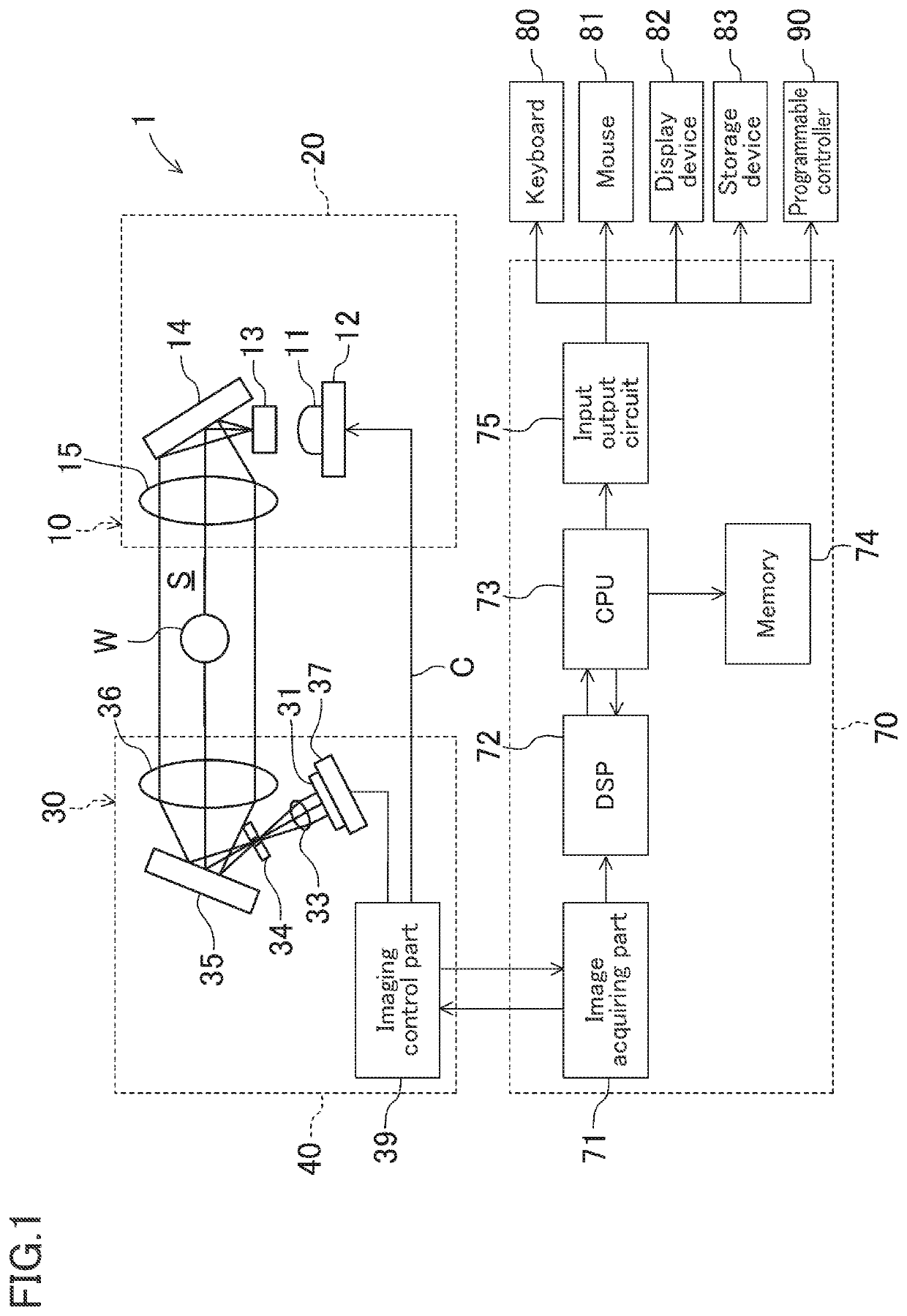
[0052]FIG. 1 schematically shows a schematic structure of an optical measurement apparatus 1 according to the embodiment of the present invention. The optical measurement apparatus 1 is a device for measuring a workpiece W which is a measuring object to be projected by measurement light, and is provided with a light projection unit 10, a light receiving unit 30, a control device 70, a keyboard 80, a mouse 81, a display device 82, and a storage device 83. Further, a programmable controller 90 is connected to the control device 70. The keyboard 80 and the mouse 81 is an example of an operation means and may be, for example, a touch panel type operation means, etc. The display de...


PUM


Abstract

An optical measurement apparatus performs an optical axis adjustment with respect to a reference surface and obtains high measurement accuracy. In an outer surface of a box-shaped light receiving housing, reference surfaces which become a reference at the time of placing the light receiving housing. In the light receiving housing, the light receiving side telecentric lens is mounted. An imaging element holder holding a two-dimensional imaging element is provided on an inner surface opposite to an introducing opening of the light receiving housing, and the two-dimensional imaging element is mounted in a manner of being capable of adjusting its position and posture.

Description

CROSS-REFERENCE TO RELATED APPLICATIONS[0001]The present application claims foreign priority based on Japanese Patent Application No. 2020-193509, filed Nov. 20, 2020, the contents of which are incorporated herein by reference.BACKGROUND OF THE INVENTIONField of the Invention[0002]The present invention relates to an optical measurement apparatus to measure a measuring object by projecting measurement light to a measurement region.Description of the Related Art[0003]For example, Japanese Patent Application Publication No. 2012-7898 discloses that the light irradiated from the light source is irradiated to an image sensor over the circumferential edge of the laminated substrate, and by projecting an image of the edge of the substrate to the image sensor, a position shift of two substrates can be detected. In the image sensor side, a telecentric lens is provided, and the image of the edge of the substrate is projected to the image sensor through the telecentric lens.SUMMARY OF THE INVE...

Claims


Application Information

Patent Timeline
IPC IPC(8): G01B11/25G02B13/22
CPCG01B11/254G02B13/22G01B11/00G01B11/27G01B11/2433G01B11/272
Inventor MINAMIGAWA, YOSHIHISASUEMURA, YUSUKETAKEI, HIDETO
Owner KEYENCE
Why Eureka
Try Eureka