Light source apparatus, method for adjusting the same and method for producing the same
a technology of light source apparatus and method, applied in the direction of lighting and heating apparatus, mountings, instruments, etc., can solve the problem of not having a single method that can solve all the problems, and achieve the effect of maintaining the positional relationship, low part count, and easy optical axis adjustmen
- Summary
- Abstract
- Description
- Claims
- Application Information
AI Technical Summary
Benefits of technology
Problems solved by technology
Method used
Image
Examples
embodiment 1
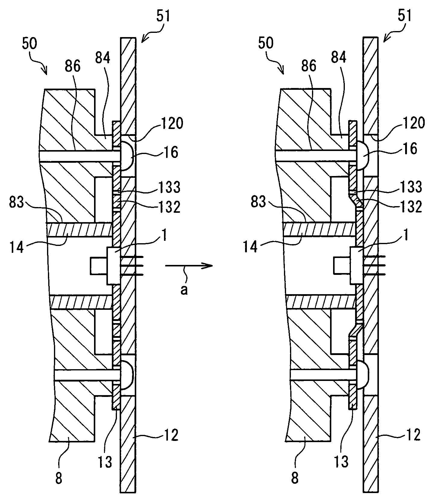
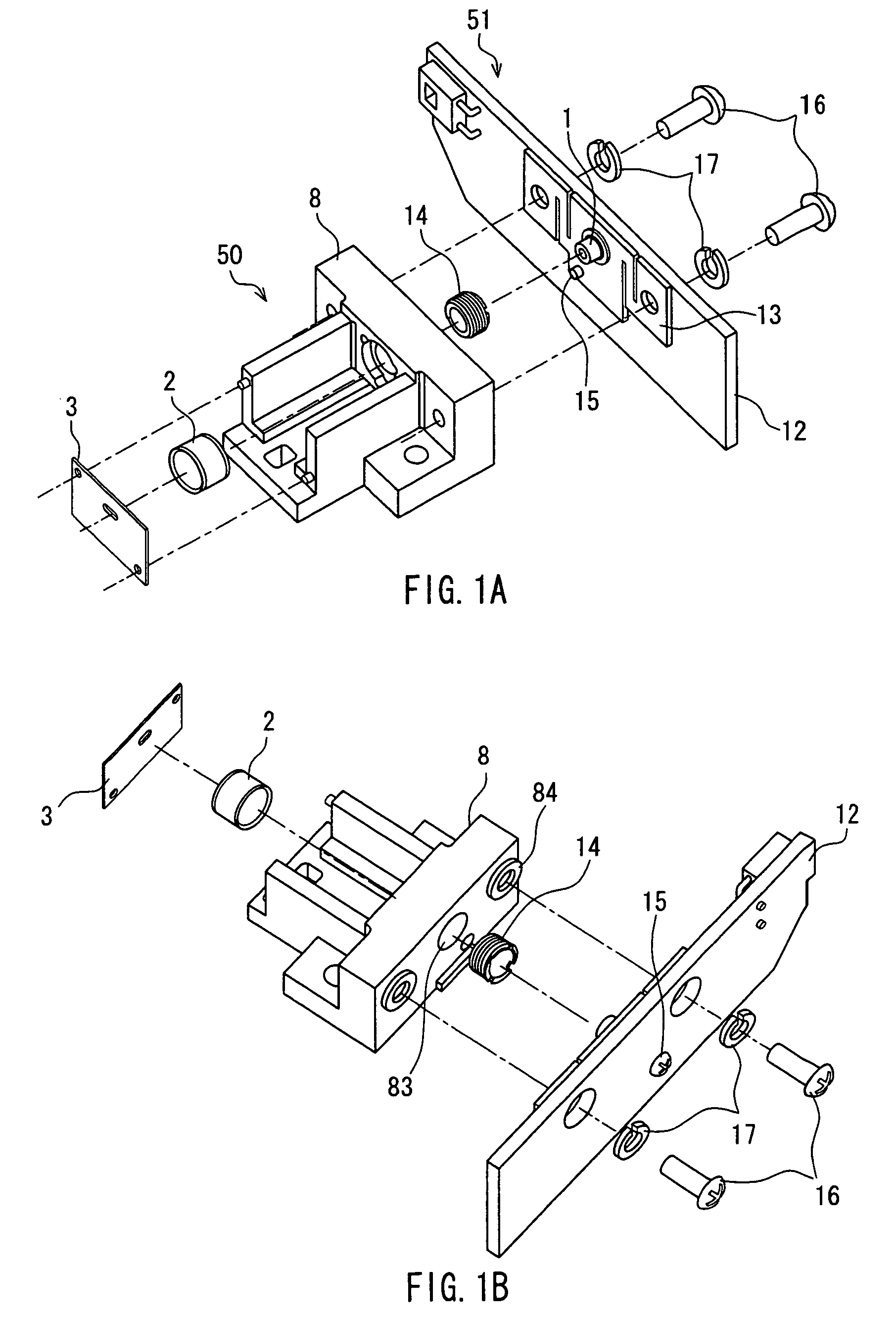
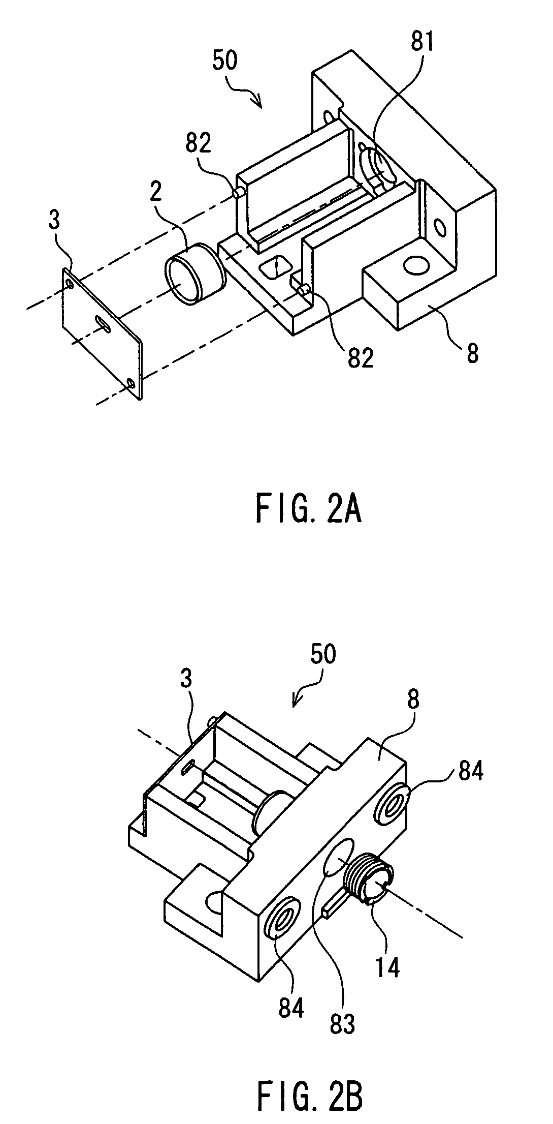
[0128]FIGS. 1A and 1B show exploded perspective views of a light source apparatus according to Embodiment 1 of the present invention. FIG. 1A is a perspective view, as viewed obliquely from the front, and FIG. 1B is a perspective view, as viewed obliquely from the back. The light source apparatus shown in FIGS. 1A and 1B is provided with a collimating lens unit 50 and a light source unit 51. The collimating lens unit 50 is provided with a collimating lens base 8, a collimating lens 2, a diaphragm 3 and an adjusting screw 14. The light source unit 51 is configured by fastening a light source supporting plate 13, to which a light source 1 is fixed, to a circuit board 12 with a fixing screw 15. The collimating lens unit 50 and the light source unit 51 are fastened with fixing screws 16.
[0129]The detailed structure of this light source apparatus is described below, while explaining its assembly procedure. FIGS. 2A and 2B are perspective views illustrating the assembly of the collimating...
embodiment 3
[0238]FIG. 19A is a perspective view showing the internal structure of an optical scanning apparatus according to Embodiment 3. FIG. 19B is a diagram schematically showing a configuration of the optical scanning apparatus according to Embodiment 3. Although the optical scanning apparatus according to Embodiment 3 is shown as an example in FIGS. 19A and 19B, a similar configuration also will be achieved by disposing the light source apparatuses according to Embodiments 1 and 2 on a frame 11. That is to say, although various configurations are possible in which the lateral position of the light source and the detailed design of other components are changed, the basic configuration will be the same as shown in FIGS. 19A and 19B.
[0239]In FIGS. 19A and 19B, the divergent light emitted from the light source (semiconductor laser) 1 passes through the collimating lens 2, the diaphragm 3 and the cylindrical lens 4, and is reflected and scanned at the polygon mirror 5. It thereafter passes th...
PUM
 Abstract
Description
Claims
Application Information
 - R&D
- Intellectual Property
- Life Sciences
- Materials
- Tech Scout
- Unparalleled Data Quality
- Higher Quality Content
- 60% Fewer Hallucinations
Browse by: Latest US Patents, China's latest patents, Technical Efficacy Thesaurus, Application Domain, Technology Topic, Popular Technical Reports.
© 2025 PatSnap. All rights reserved.Legal|Privacy policy|Modern Slavery Act Transparency Statement|Sitemap|About US| Contact US: help@patsnap.com


