Frame of photovoltaic panel and l-shaped corner joint thereof
- Summary
- Abstract
- Description
- Claims
- Application Information
AI Technical Summary
Benefits of technology
Problems solved by technology
Method used
Image

Examples
embodiment 1
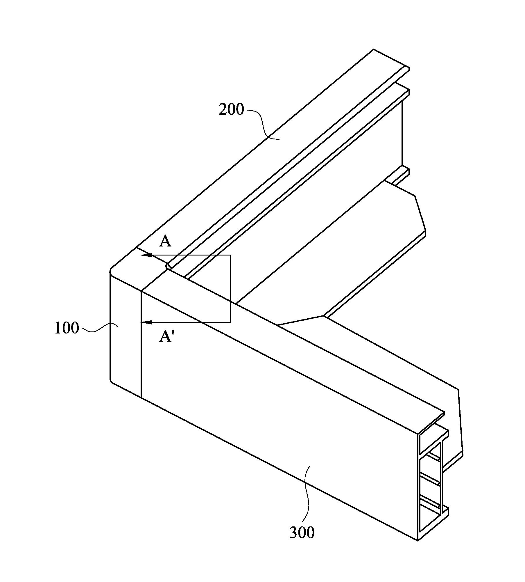
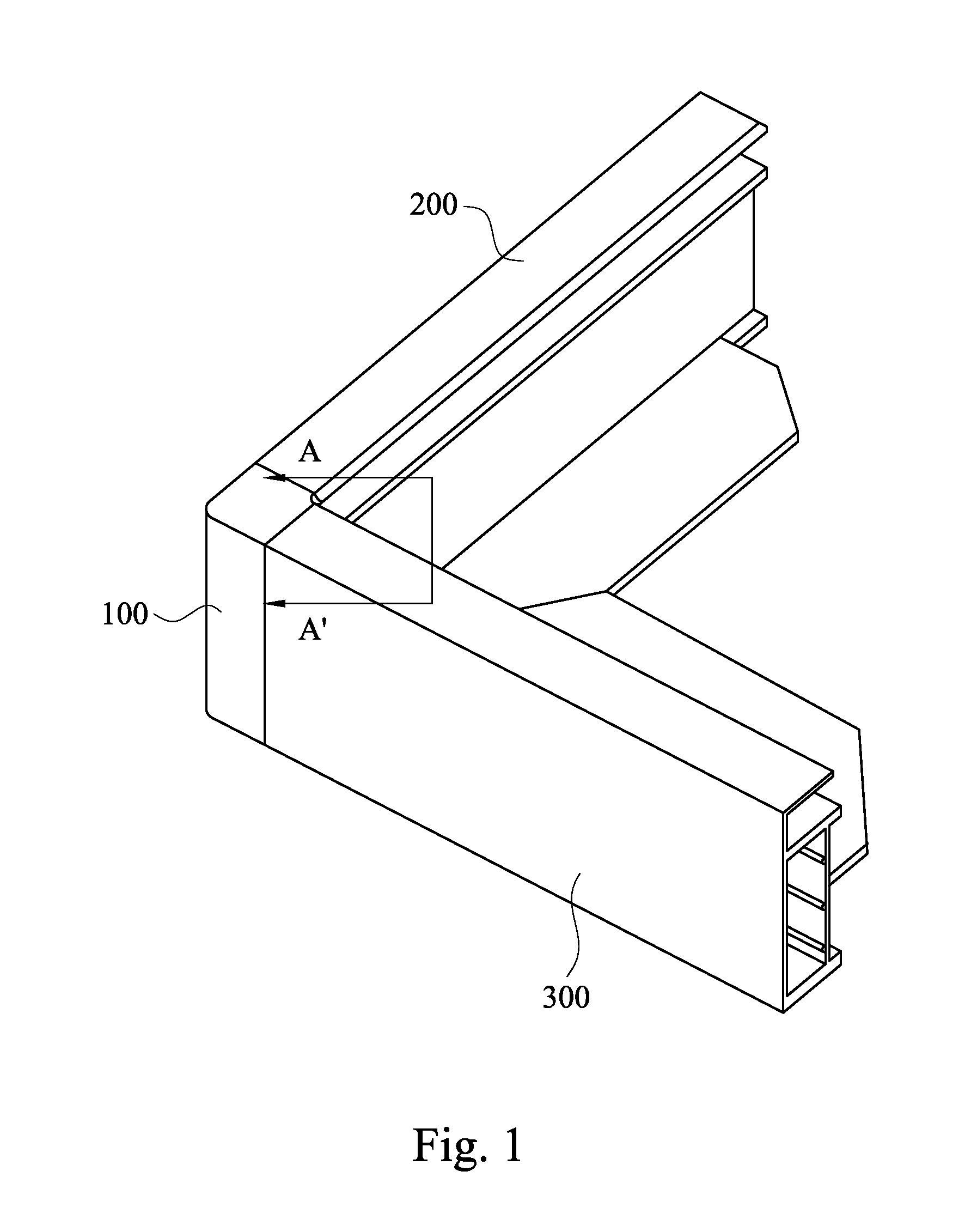
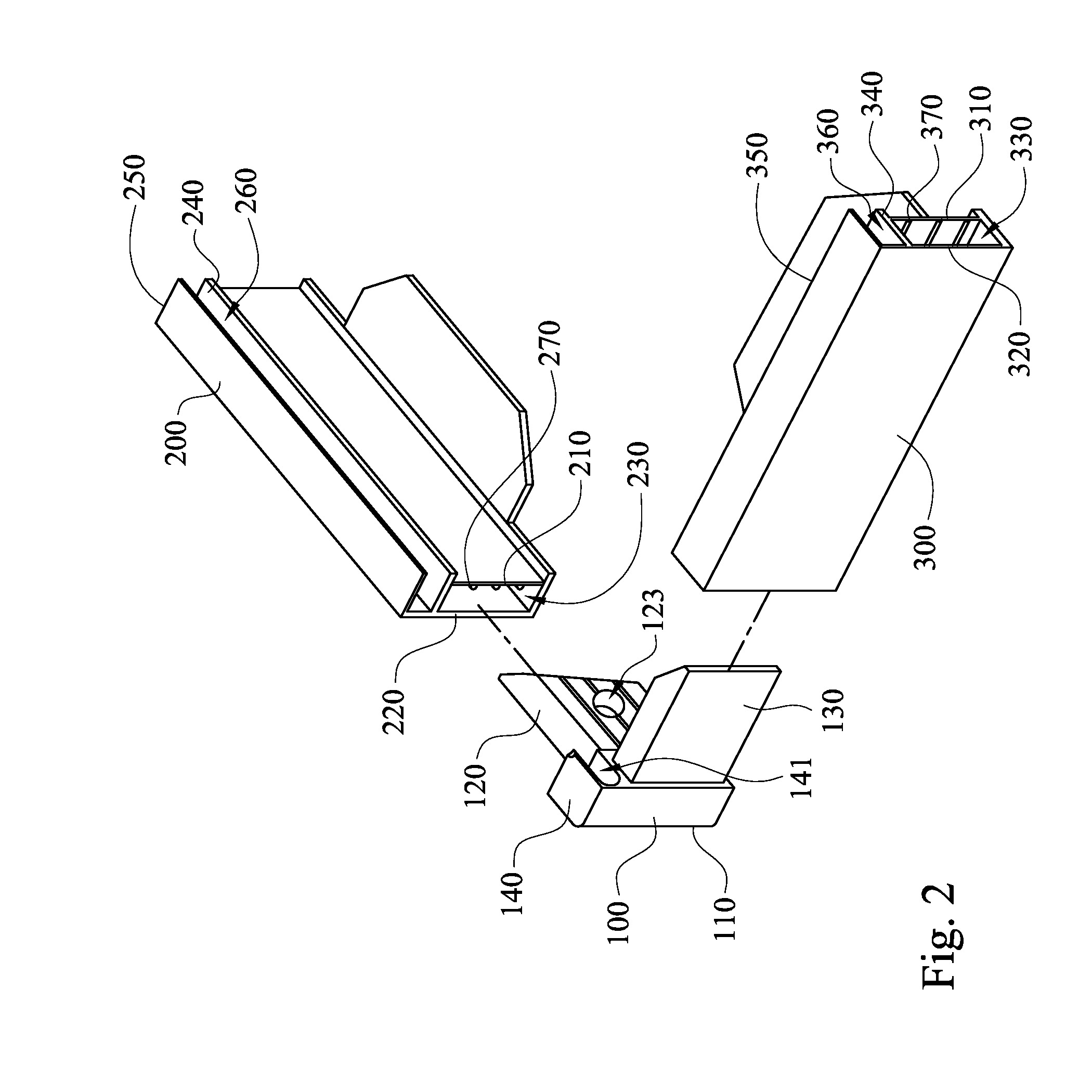
[0023]FIG. 1 is a perspective view of the frame of the photovoltaic panel in accordance with one embodiment of the present invention. FIG. 2 is an explosive view of the frame shown in FIG. 1. As shown in FIGS. 1 and 2, in this embodiment, the frame of the photovoltaic panel includes a L-shaped corner joint 100, a first frame body 200 and a second frame body 300. The L-shaped corner joint 100 is connected between the first frame body 200 and the second frame body 300. In particular, as shown in FIG. 2, the L-shaped corner joint 100 includes a support 110, a first joint arm 120 and a second joint arm 130. The first joint arm 120 and the second joint arm 130 are respectively disposed on different surfaces of the support 110. The first frame body 200 has a first inner frame plate 210 and a first outer frame plate 220. The first inner frame plate 210 and the first outer frame plate 220 are spatially separated and define a first engaging groove 230 therebetween. The first joint arm 120 is...
embodiment 2
[0040]FIG. 6 is a cross-sectional view of the L-shaped corner joint 100a in accordance with the second embodiment of the present invention. The main difference between this embodiment and the first embodiment is that: the first joint arm 120a and the second joint arm 130b respectively have a first riveting hole 123a and a second riveting hole 133a. The first riveting hole 123a crosses the first inner surface 121 and the first outer surface 122. The second riveting hole 133a crosses the second inner surface 131 and the second outer surface 132. In other words, the first riveting hole 123a and the second riveting hole 133a are both through holes, so as to facilitate the riveting process.
embodiment 3
[0041]FIG. 7 is a perspective view of the L-shaped corner joint 100b in accordance with the third embodiment of the present invention. The main difference between this embodiment and the first embodiment is that: the first joint arm 120b and the second joint arm 130b respectively have plural (such as four) first riveting holes 123a and plural (such as four) second riveting holes 133a. Therefore, the embodiment can be applied on different riveting machine, such as the riveting machine 400 having plural (such as four) first rivets 410 and plural (such as four) second rivets 420 (See FIG. 3).
[0042]Moreover, in this embodiment, the first joint arm 120b includes four first guiding rails 124b, and the second joint arm 130 includes four second guiding rails 134, in which the amount is different from the first guiding rails 124 and the second guiding rails 134 in the first embodiment.
PUM
 Abstract
Description
Claims
Application Information