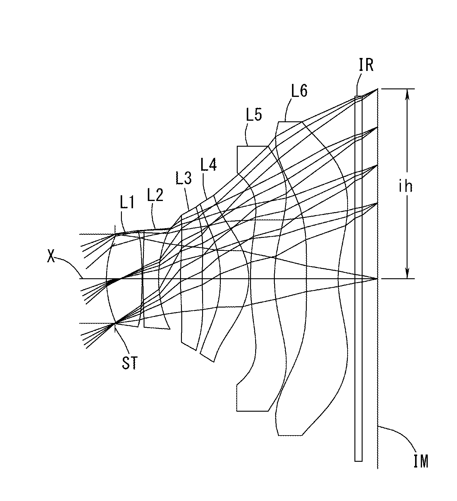
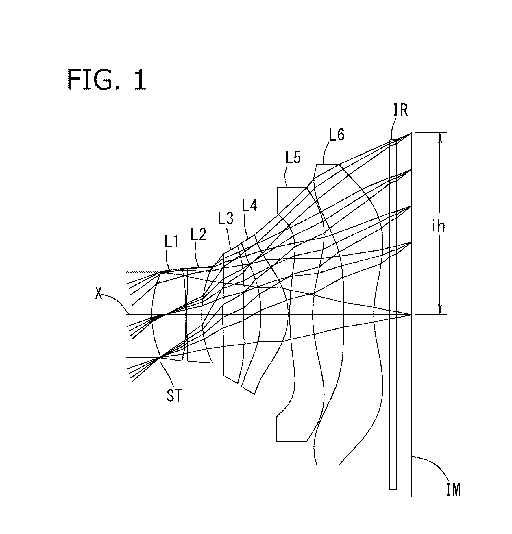
Imaging lens

a technology of image sensor and lens, applied in the field of image lens, can solve the problems of inability to meet the demand satisfactorily, inability to deliver satisfactory optical performance, and difficulty in delivering the same level of high optical performance as in a small image sensor, so as to achieve enhanced telephoto ability and prevent the increase of total track length

Active Publication Date: 2014-12-04
TOKYO VISIONARY OPTICS CO LTD
View PDF1 Cites 57 Cited by
  • Summary
  • Abstract
  • Description
  • Claims
  • Application Information

AI Technical Summary

Benefits of technology

[0059]The conditional expression (13) defines an adequate range for the ratio of the composite positive focal length of the first to fourth lenses to the focal length of the overall optical system of the imaging lens, and the conditional expression (14) defines an adequate range for

Problems solved by technology

However, in the conventional techniques, it is difficult to meet this demand satisfactorily.
If a conventional imaging lens is used in a large image sensor, since its optical system should be large, the following problem arises that various aberrations become more serious and it is very difficult to deliver the same level of high optical performance as in a small image sensor.
In addition, when the lens is designed to provide a wide field of view, correction of aberrations may be very difficult, particularly in the peripheral area, regardless of image sensor size and it may be impossible to deliver satisfactory optical performance.
However, it cannot meet the recent demand for a wider field of view.
However, if an imaging lens uses five constituent lenses, its ability to correct aberrations is limited and it is difficult to apply the imaging lens to a higher resolution apparatus as mentioned above.
However, its half field of view is about 33 de

Method used


Image

  • Imaging lens
  • Imaging lens
  • Imaging lens

Examples


example 1

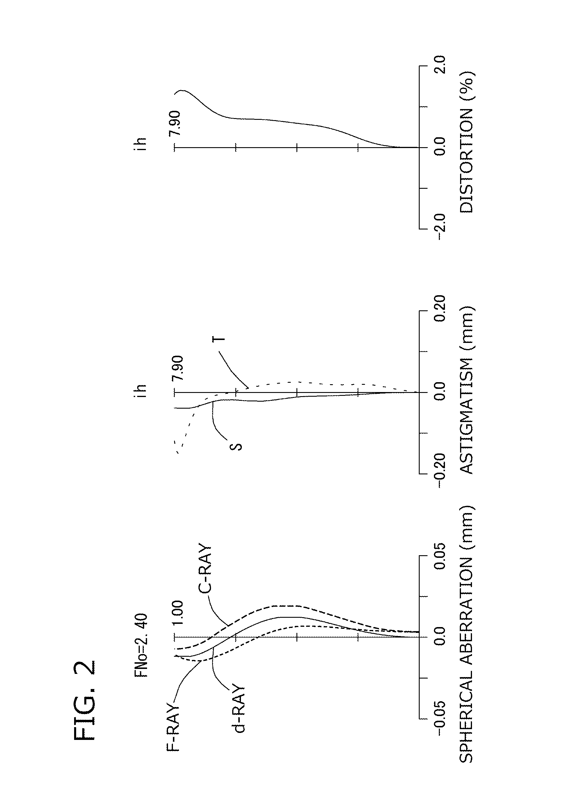
[0116]The basic lens data of Example 1 is shown below in Table 1.

TABLE 1Example 1in mmf = 8.881Fno = 2.40ω(°) = 41.3ih = 7.902Surface DataCurvatureSurfaceRefractiveAbbeSurface No. iRadius rDistance dIndex NdNumber vd(Object Surface)InfinityInfinity 1 (Stop)Infinity−0.355 2*4.2751.4841.543855.57 3*−15.0550.040 4*46.7400.6501.614225.58 5*5.1590.913 6*13.2630.9091.534656.16 7*24.8710.751 8*−5.6001.1821.534656.16 9*−2.6700.07010*12.4431.0001.614225.5811*6.1231.33012*81.9181.3251.534656.1613*4.7250.60014Infinity0.3001.567037.8015Infinity0.746Image PlaneInfinityConstituent Lens DataLensStart SurfaceFocal Length126.29324−9.4983651.739488.369510−20.885612−9.435Composite Focal Lengthf123455.88f56−6.17Aspheric Surface Data2nd Surface3rd Surface4th Surface5th Surface6th Surface7th Surfacek0.000E+000.000E+000.000E+000.000E+000.000E+000.000E+00A4−7.869E−04  7.232E−034.714E−03−2.930E−03  −8.477E−03  −7.907E−03  A6−2.818E−04  −2.373E−03  −2.894E−04  2.261E−036.556E−041.565E−04A84.033E−05−1.980E−04...

example 2

[0120]The basic lens data of Example 2 is shown below in Table 2.

TABLE 2Example 2in mmf = 6.764Fno = 2.40ω(°) = 41.2ih = 5.992Surface DataCurvatureSurfaceRefractiveAbbeSurface No. iRadius rDistance dIndex NdNumber vd(Object Surface)InfinityInfinity 1 (Stop)Infinity−0.185 2*4.0531.0661.543855.57 3*−8.8160.101 4*35.0890.5001.614225.58 5*4.1550.648 6*8.5440.7101.534656.16 7*29.0840.609 8*−4.0381.3051.534656.16 9*−2.0160.05310*11.9030.7901.614225.5811*5.0030.60612*6.3661.0971.534656.1613*2.5250.60014Infinity0.3001.567037.8015Infinity0.850Image PlaneInfinityConstituent Lens DataLensStart SurfaceFocal Length125.25924−7.7203622.360486.148510−14.692612−8.694Composite Focal Lengthf123417.09f56−5.12Aspheric Surface Data2nd Surface3rd Surface4th Surface5th Surface6th Surface7th Surfacek0.000E+000.000E+000.000E+000.000E+000.000E+000.000E+00A4−2.806E−03  1.014E−023.547E−03−1.407E−02  −1.733E−02  −8.408E−03  A6−1.408E−03  −6.129E−03  6.567E−047.185E−037.447E−04−5.976E−04  A81.483E−04−8.568E−04  −...

example 3

[0124]The basic lens data of Example 3 is shown below in Table 3.

TABLE 3Example 3in mmf = 6.765Fno = 2.40ω(°) = 41.2ih = 5.992Surface DataCurvatureSurfaceRefractiveAbbeSurface No. iRadius rDistance dIndex NdNumber vd(Object Surface)InfinityInfinity 1 (Stop)Infinity−0.185 2*4.0451.1071.543855.57 3*−9.4090.092 4*27.8490.5001.614225.58 5*4.1460.664 6*9.2630.7101.534656.16 7*37.9160.583 8*−4.0001.3201.534656.16 9*−2.0160.05310*12.0180.7901.614225.5811*5.1290.62612*5.9031.0451.534656.1613*2.4400.70014Infinity0.3001.564051.3015Infinity0.778Image PlaneInfinityConstituent Lens DataLensStart SurfaceFocal Length125.35724−7.9943622.730486.172510−15.234612−8.692Composite Focal Lengthf123416.97f56−5.20Aspheric Surface Data2nd Surface3rd Surface4th Surface5th Surface6th Surface7th Surfacek0.000E+000.000E+000.000E+000.000E+000.000E+000.000E+00A4−2.321E−03  1.017E−022.905E−03−1.319E−02  −1.643E−02  −8.716E−03  A6−1.169E−03  −5.693E−03  7.463E−046.718E−037.583E−04−4.328E−04  A81.335E−04−9.045E−04  −...


PUM


Abstract

A compact high-resolution imaging lens which provides a wide field of view of 80 degrees or more and corrects various aberrations properly. Designed for a solid-state image sensor, the imaging lens includes constituent lenses arranged in the following order from an object side to an image side: a first positive (refractive power) lens having a convex object-side surface; a second negative lens having a concave image-side surface; a third positive lens as a double-sided aspheric lens having a convex object-side surface; a fourth positive lens having a convex image-side surface; a fifth lens as a double-sided aspheric lens having a concave image-side surface; and a sixth negative lens having a concave image-side surface. The image-side surface of the sixth lens has an aspheric shape with a pole-change point in a position off an optical axis.

Description

[0001]The present application is based on and claims priority of Japanese patent application No. 2013-116152 filed on May 31, 2013, and Japanese patent application No. 2014-035806 filed on Feb. 26, 2014, the entire contents of which are hereby incorporated by reference.BACKGROUND OF THE INVENTION[0002]1. Field of the Invention[0003]The present invention relates to imaging lenses which form an image of an object on a solid-state image sensor such as a CCD sensor or a C-MOS sensor used in a compact image pickup device. More particularly, the invention relates to imaging lenses which are built in image pickup devices mounted in highly functional products such as smart TVs and 4K TVs, information terminals such as game consoles and PCs, and mobile terminals such as smart phones, mobile phones and PDAs (Personal Digital Assistants).[0004]2. Description of the Related Art[0005]In recent years, highly functional products, such as a smart TV as a TV with a personal computer function and a 4...

Claims


Application Information

Patent Timeline
IPC IPC(8): G02B13/00
CPCG02B13/0045G02B3/04G02B5/005G02B9/62G02B13/0015G02B13/002G02B13/16G02B13/18G02B27/0025H05K999/99
Inventor SEKINE, YUKIO
Owner TOKYO VISIONARY OPTICS CO LTD
Why Eureka
Try Eureka