Receiver system for a fresnel solar plant

Inactive Publication Date: 2014-12-11
RIOGLASS SOLAR HLDG SA
View PDF9 Cites 4 Cited by
  • Summary
  • Abstract
  • Description
  • Claims
  • Application Information

AI Technical Summary

Benefits of technology

[0036]The first joint is preferably formed as a solid joint. In this embodiment, the joint can be formed by a monolithic solid that is flexible, however, due to its flat cross section. This form of the joint ha

Problems solved by technology

However, the mirrors also expand to a significant extent due to the he

Method used


Image

  • Receiver system for a fresnel solar plant
  • Receiver system for a fresnel solar plant
  • Receiver system for a fresnel solar plant

Examples


first embodiment

[0079]FIG. 9 shows, in a schematically very simplified form, the optical components of the receiver system according to the invention according to a The receiver tube 906 having an absorber tube 908 and a sleeve tube 910, which surrounds the absorber tube 908 concentrically, can be seen therein. Also counted among the optical components is the mirror array 912 above the receiver tube 906, which is separated in the longitudinal direction into the two first and second mirror elements 932 and 934 with a gap 936 lying in between, directly over the receiver tube 906, which is closed optically at least partially by a mirror segment 968. Closed optically at least partially in this case means that, considered in cross section, an air gap 970 remains between the first mirror element 932 and the mirror segment 968 as well as between the second mirror element 934 and the mirror segment 968.

[0080]The gap 936 between the first and the second mirror elements 932 and 934 serves as the opening thr...

third embodiment

[0085]the optical components of the receiver system according to the invention is shown schematically in FIG. 11. With respect to the mirror array 1112, this essentially corresponds to the embodiment of FIG. 9. As it was therein, the mirror array is composed of a first, a second, and a third mirror element 1132, 1134, and 1171.

[0086]A difference from the example of embodiment in FIG. 9 consists of a modified shape of the receiver tube 1106, in which the absorber tube 1108 is disposed eccentrically in the sleeve tube 1110. Stated more precisely, the absorber tube 1108 is shifted up, so that the gap between the lateral surface of the absorber tube 1108 and the lateral surface of the sleeve tube 1110 is reduced on the upper side facing the third mirror element 1171. In this way, radiation losses are minimized; see also FIG. 12A.

[0087]In addition, a first profile element 1138, which is associated with the first mirror element 1132; a second profile element 1140, which is associated with...

second embodiment

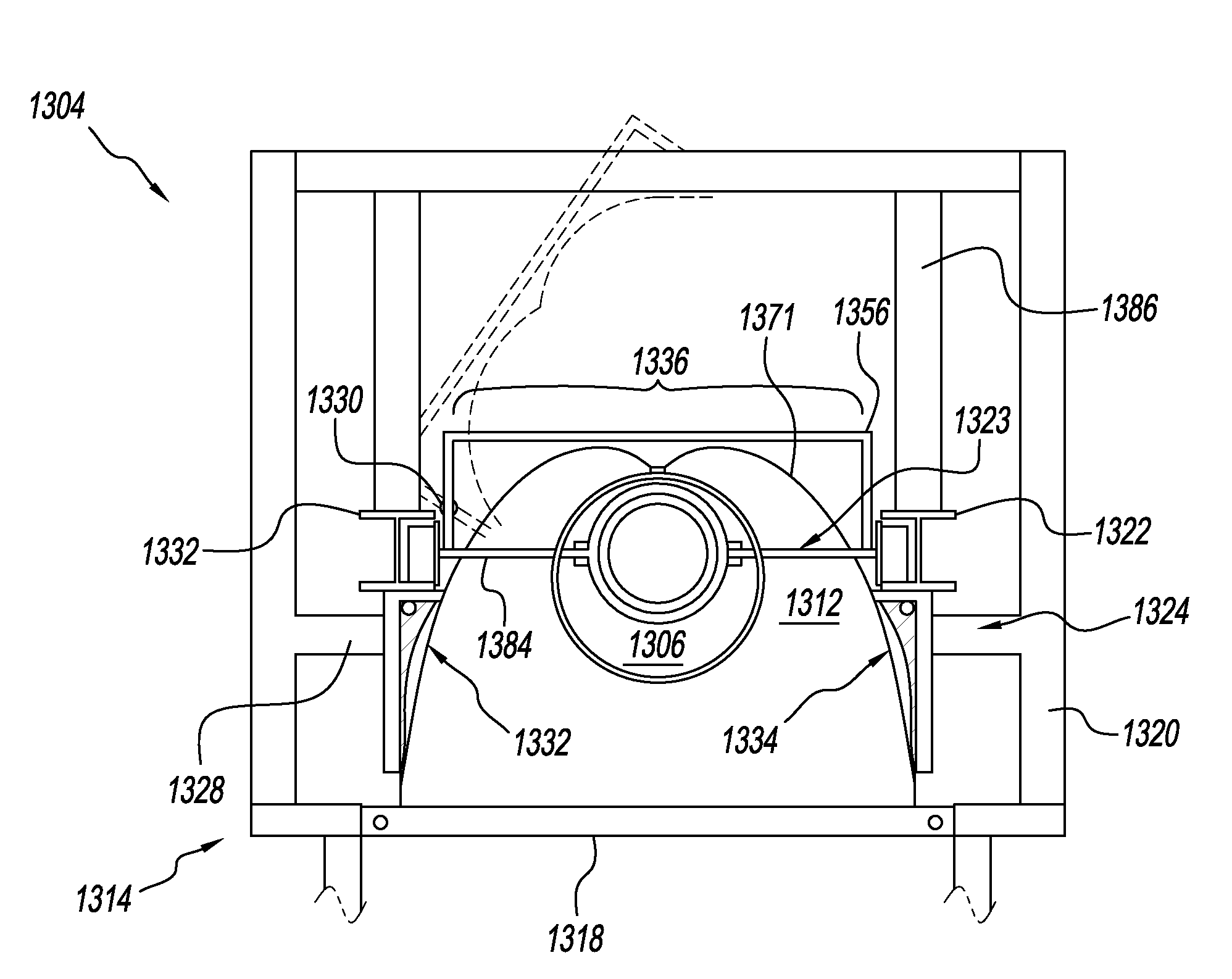
[0095]FIG. 13 shows the receiver system 1304 according to the invention, having a receiver tube 1306 of the type described above. Essential differences compared to the embodiment discussed above are to be found in the configuration of the mirror array 1312, the support frame 1314, and the first and second suspensions, and only these differences will be discussed below.

[0096]The support frame 1314 has a crosswise support 1318 and a frame element 1320 attached thereon. In addition, the support frame 1314 has a first suspension 1323 for holding the receiver tube 1306 and a second suspension 1324 for holding the mirror array 1312, more precisely, a first and a second mirror element 1332, 1334, and the associated first and second profile elements 1338, 1340. The two suspensions 1323 and 1324 are connected to the frame element 1320 independently from one another. Two longitudinal support members 1322 running parallel to the receiver tube 1306 and the mirror array 1312, but this time horiz...


PUM


Abstract

A receiver system for a Fresnel solar plant is provided that includes an absorber tube defining a longitudinal direction, a mirror array that runs parallel to the longitudinal direction and is used for concentrating light beams onto the absorber tube, and a support frame for the absorber tube and the mirror array. A first suspension for holding the absorber tube and a second suspension for holding the mirror array or at least parts of the mirror array are independently mounted on the support frame. The first suspension has first compensation device while the second suspension has second compensation device. The first and second compensation devices allow for different expansions of the absorber tube and the mirror array or at least parts of the mirror array in the longitudinal direction.

Description

CROSS REFERENCE TO RELATED APPLICATIONS[0001]This application is a continuation of International Application No. PCT / EP2012 / 074907 filed Dec. 10, 2012, which claims the benefit under 35 U.S.C. §119(a) of German Patent Application No. 10 2011 088 829.2, filed Dec. 16, 2011, the entire contents of which are incorporated herein by reference.BACKGROUND OF THE INVENTION[0002]1. Field of the Invention[0003]The invention relates to a receiver system for a Fresnel solar plant having an absorber tube defining a longitudinal direction, a mirror array parallel to the longitudinal direction as a secondary concentrator for the concentration of light beams on the absorber tube, and a support frame for the receiver tube and the mirror array.[0004]2. Description of Related Art[0005]The generic receiver system is part of a solar power plant, which has, in addition, a primary concentrator in the form of a field of rows of mirrors mounted in parallel close to the ground, which concentrate solar rays o...

Claims


Application Information

Patent Timeline
IPC IPC(8): F24J2/12F24S10/40F24S20/20F24S23/70F24S23/71F24S23/74F24S23/79
CPCF24J2/12Y02E10/44F24S10/45F24S20/20F24S23/80F24S23/74F24S23/79F24S40/80F24S2023/834F24S2023/872F24S2023/876F24S23/71Y02E10/40
Inventor SAUERBORN, ANDREASGNAEDIG, TIMKUCKELKORN, THOMASBRENGELMANN, TIM
Owner RIOGLASS SOLAR HLDG SA
Why Eureka
Try Eureka