Mono bearing one piece core solenoid

a solenoid and mono bearing technology, applied in the field of solenoid valves, can solve the problems of contaminants in transmission fluid generated by metal particles, and contaminants can often become lodged within the solenoid valve, and achieve the effect of enhancing the flow density of the solenoid valv

Active Publication Date: 2014-12-11
BORGWARNER INC
View PDF12 Cites 17 Cited by
  • Summary
  • Abstract
  • Description
  • Claims
  • Application Information

AI Technical Summary

Benefits of technology

[0005]To make manifest the above noted and other desires, a revelation of the present invention is brought forth. In a preferred embodiment of the present invention, a solenoid valve is provided which has a unitary case, flux tube and pole piece. Accordingly, discontinuities between the casing, flux tube and pole piece are eliminated and operation of the solenoid valve is more consistent over time. Additionally, other operational enhancements are made such that the flux density of the solenoid valve is enhanced in a manner to be later described.

Problems solved by technology

During operation of the vehicle and due to wear of the various gears, shafts and bearings of the transmission, metallic particles are generated as contaminants in the transmission fluid.
These contaminants can often become lodged within the solenoid valves since they are attracted to the magnetic fields which permeate the solenoid valves.

Method used


Image

  • Mono bearing one piece core solenoid
  • Mono bearing one piece core solenoid
  • Mono bearing one piece core solenoid

Examples


Embodiment Construction

[0012]The following description of the preferred embodiment(s) is merely exemplary in nature and is in no way intended to limit the invention, its application, or uses.

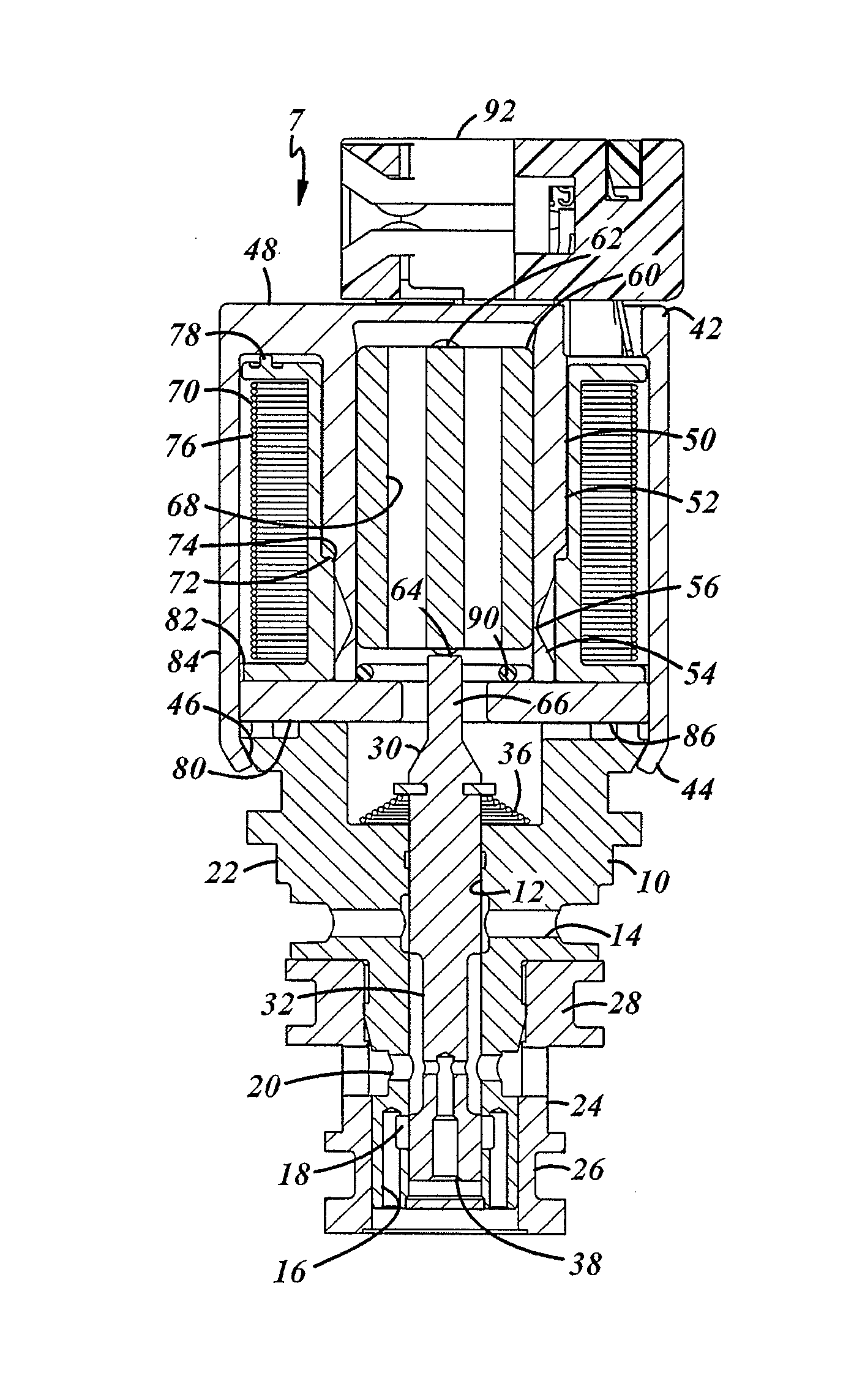
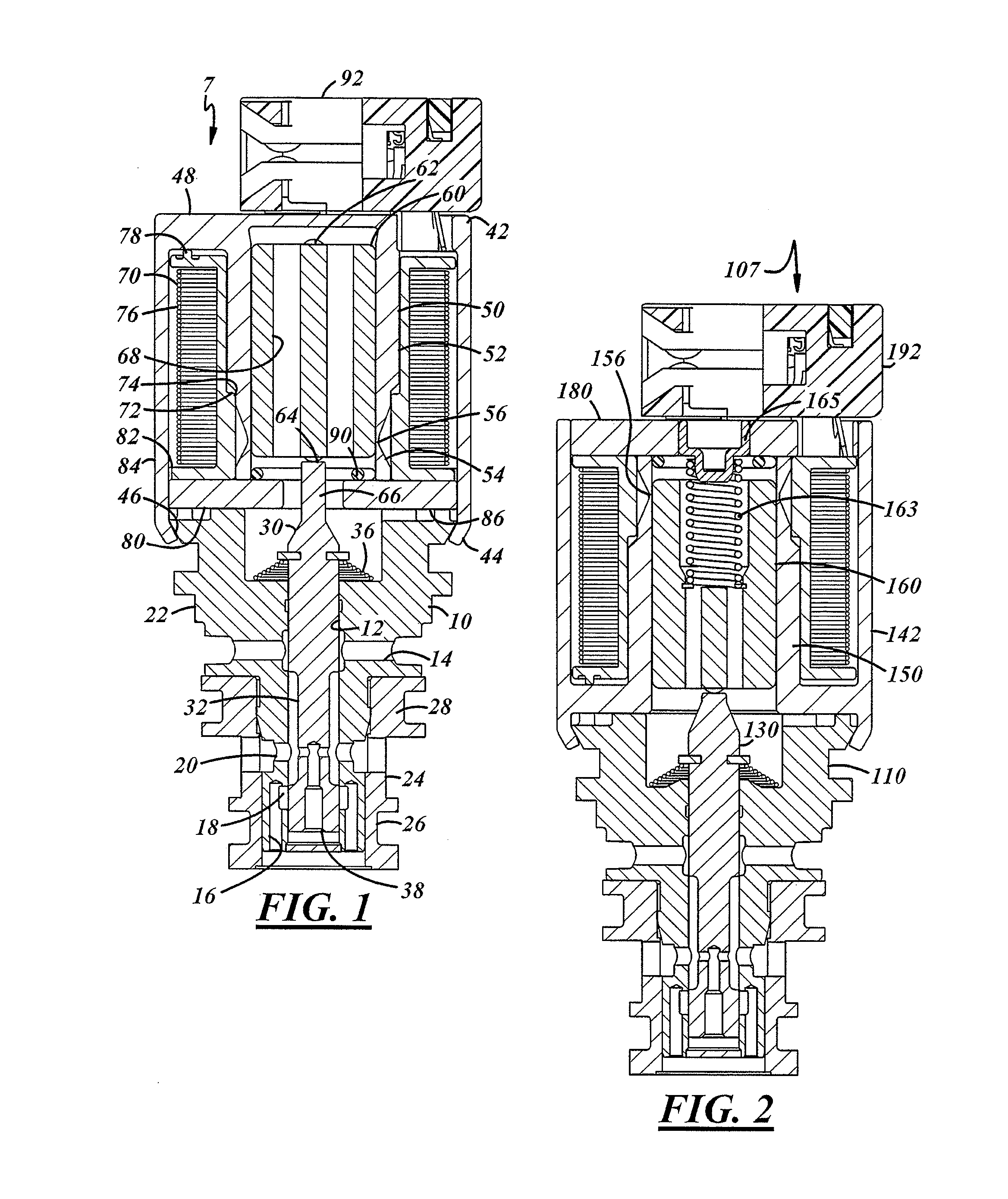
[0013]Referring to FIG. 1, an immersable solenoid valve 7 according to the present invention can have a valving member including a hydraulic body 10. The hydraulic body 10 has an axial generally tubular passage 12. The hydraulic body 10 has a transverse cross bore 14 for connection with exhaust pressure or a sump. The hydraulic body 10 additionally has a series of non-concentric axial bores 16 which intersect an enlarged diameter portion 18 to provide a fluid path which is connected with supply pressure. A multi-dimensional cross bore 20 is provided for inlet / outlet connection with a desired control pressure. The hydraulic body 10 has a metallic primary body 22 and has a lower tip covered by an outer sleeve member 24 having annular grooves 26 and 28 for placement of sealing members (not shown).

[0014]Slidably mounted w...


PUM


Abstract

A solenoid valve assembly is provided which includes a ferromagnetic casing forming a generally tubular envelope, a flux tube integrally formed with the casing and extending axially generally there from defining and axially extending annular space there between, the flux tube having a first portion connected with the casing and a second portion integral with the first portion be divided there from by a flux choke, and also including an armature aligned and slidably mounted within the flux tube for imparting movement to a valve member.

Description

FIELD OF THE INVENTION[0001]The present invention relates to solenoid valves, especially solenoid valves utilized in the control of hydraulic control fluids and such valves that can function submerged in hydraulic fluid.BACKGROUND OF THE INVENTION[0002]Automotive automatic transmissions typically have a plurality of components including torque convertors and clutches wherein states of engagement and disengagement must be controlled. Initially such components were controlled with fluid pressure logic components. In an era approximately beginning in the 1980's, more and more automotive transmissions have been brought forth wherein the control of the torque convertor and clutches has been taken over by electronic logic controls which utilize solenoid valves to control the hydraulic control fluid which actuates or relieves the operation of the various fluid pressure actuated components of the transmission. Currently, many of these solenoid valves are hermetically sealed within the trans...

Claims


Application Information

Patent Timeline
Patent Type & Authority Applications(United States)
IPC IPC(8): F16K31/06F16K3/26
CPCF16K31/0668F16K3/26F16K31/0675H01F7/1638H01F7/081H01F7/1607F16K31/0613F16K27/048
Inventor HOLMES, GARRETT R.MILLS, DAVID C.
Owner BORGWARNER INC
Why Eureka
Try Eureka