Adjustable three-stage light emitting diode bulb

Inactive Publication Date: 2014-12-11
HUANG TAI HSIANG +1
View PDF11 Cites 1 Cited by
  • Summary
  • Abstract
  • Description
  • Claims
  • Application Information

AI Technical Summary

Benefits of technology

[0009]The primary object of the present invention is to provide a three-stage power adjustable Light Emitting Diode bulb wherein the electric energy consumption of the Light Emitting Diode

Problems solved by technology

However, the Tungsten-filaments consume significant electric power energy and have shorter life.
The conventional th

Method used


Image

  • Adjustable three-stage light emitting diode bulb
  • Adjustable three-stage light emitting diode bulb
  • Adjustable three-stage light emitting diode bulb

Examples


Embodiment Construction

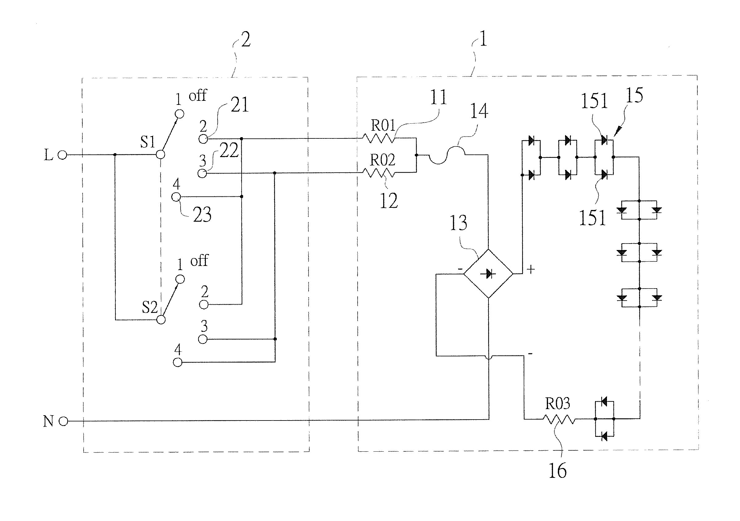
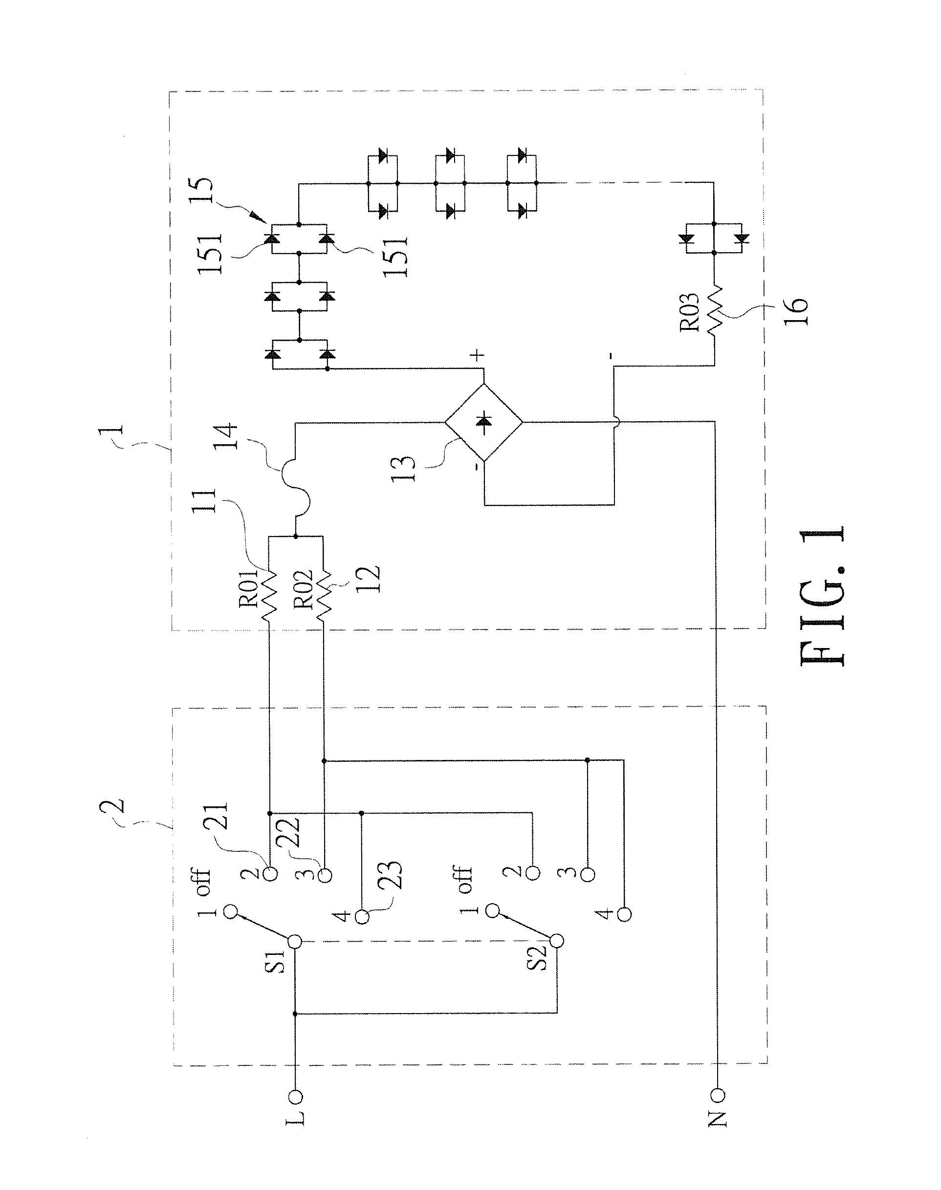
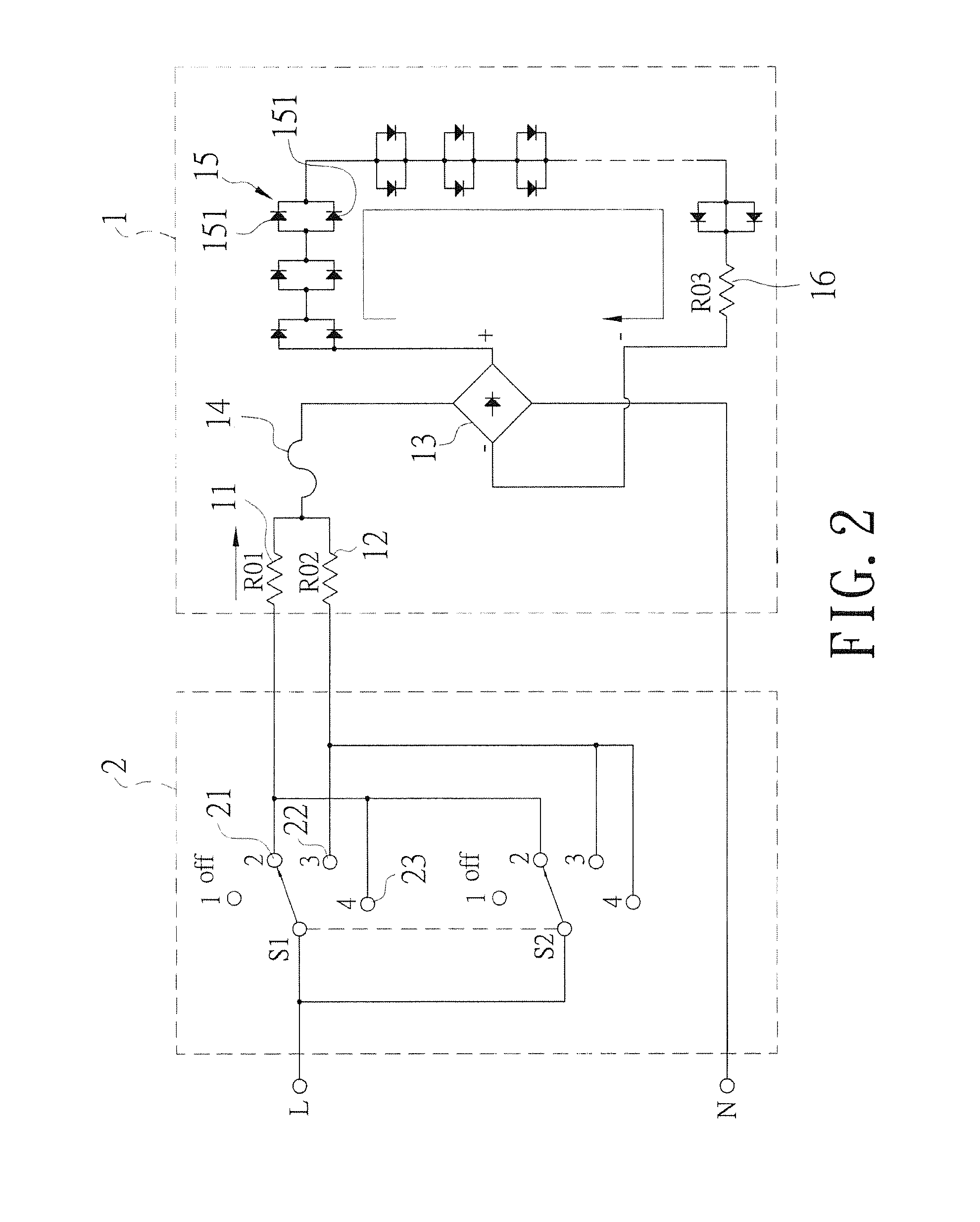
[0016]Referring to FIG. 1, a three-stage power adjustable Light Emitting Diode bulb 1 of the present invention is cooperated with a three-stage switch 2 and comprises a first resistance 11 and a second resistance 12 which is electrically connected to the first resistance 11 in parallel. The first resistance 11 and the second resistance 12 are connected to a rectifier 13. A fuse 14 is connected between the first and second resistances 11, 12 and the rectifier 13. Multiple Light Emitting Diode units 15 and a limiting resistance 16 are connected between positive and negative poles of the rectifier 13. The Light Emitting Diode units 15 each have multiple Light Emitting Diodes 151.

[0017]A first switch 21 of the three-stage switch 2 is connected to the first resistance 11 of the three-stage power adjustable Light Emitting Diode bulb 1. A second switch 22 of the three-stage switch 2 is connected to the second resistance 12 of the three-stage power adjustable Light Emitting Diode bulb 1. A ...


PUM


Abstract

A three-stage power adjustable Light Emitting Diode bulb includes a first resistance and a second resistance which is electrically connected to the first resistance in parallel. The first resistance and the second resistance are connected to a rectifier. Multiple Light Emitting Diode units and a limiting resistance are connected between the positive and negative poles of the rectifier. The Light Emitting Diode units each have multiple Light Emitting Diodes. The electric energy consumption of the Light Emitting Diode bulb is reduced and the life of use of the Light Emitting Diode bulb is prolonged. The resistance value of the first and second resistance can be adjusted to have different luminous powers.

Description

BACKGROUND OF THE INVENTION[0001]1. Fields of the Invention[0002]The present invention relates to a Light Emitting Diode bulb (LED bulb), and more particularly, to a three-stage power adjustable Light Emitting Diode bulb with adjustable resistances to have different output power.[0003]2. Descriptions of Related Art[0004]The conventional three-stage adjustable bulb 31 comprises a first Tungsten-filament 311 of lower power and a second Tungsten-filament 312 of high power located in the bulb 31. The circuit for the conventional three-stage adjustable bulb 31 is disclosed in FIG. 5. A three-stage switch 32 is cooperated with the three-stage adjustable bulb 31. The first switch of the three-stage switch 32 is connected to the first Tungsten-filament 311 and the second switch of the three-stage switch 32 is connected to the second Tungsten-filament 312. The third switch of the three-stage switch 32 is connected to the first and second Tungsten-filaments 311, 312 in parallel. When the user...

Claims


Application Information

Patent Timeline
IPC IPC(8): H05B33/08H05B44/00
CPCH05B33/0845H05B45/37
Inventor HUANG, TAI-HSIANGHUANG, KUAN-HSIANG
Owner HUANG TAI HSIANG
Why Eureka
Try Eureka