
Power supply circuit and power supply method

a power supply circuit and power supply method technology, applied in the direction of electric variable regulation, process and machine control, instruments, etc., can solve the problems of inconvenience for people's use, limited capacity of electronic devices, and relatively large energy consumption, so as to reduce the consumption of electric energy, and reduce the effect of large energy consumption

Active Publication Date: 2018-01-02
BOE TECH GRP CO LTD +1
View PDF19 Cites 0 Cited by
  • Summary
  • Abstract
  • Description
  • Claims
  • Application Information

AI Technical Summary

Benefits of technology

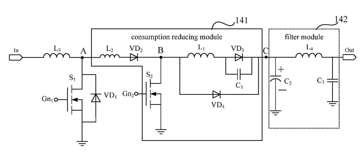
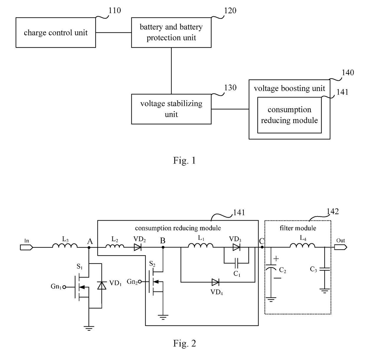
The present invention provides a power supply circuit and method that reduces electric energy consumption by eliminating current flow when a power device is turned on or off. This is achieved by incorporating a consumption reducing module in the voltage boosting unit, resulting in a more efficient and effective power supply.

Problems solved by technology

However, the built-in batteries of these electronic devices have limited capacities, which may bring inconvenience to people's use sometimes. The mobile power supply as a portable charger has the advantages of having a small volume and being safe and reliable, and can charge the device at any time and any place.
The above mobile power supply at least has the following defect: when the mobile power supply charges the electronic device, there will be a part of electric energy consumed within the mobile power supply, which results in a relatively large energy consumption.

Method used


Image

  • Power supply circuit and power supply method
  • Power supply circuit and power supply method
  • Power supply circuit and power supply method

Examples


Embodiment Construction

[0038]Next, the exemplary embodiments will be explained in detail, the examples thereof are indicated in the drawings. When the following description relates to the drawings, unless otherwise indicated, the same number in different drawings represents the same or similar element. The implementing modes described in the following exemplary embodiments do not represent all implementing modes consistent with the present invention. On the contrary, they are only examples of devices and methods consistent with some aspects of the present invention.

[0039]The transistors used in all the embodiments of the present invention can all be thin film transistors or field effect transistors or other devices with the same properties. According to the function in the circuit, the transistors used in the embodiments of the present invention are mainly switch transistors. Since the source and the drain of the switch transistor used here are symmetric, the source and the drain thereof can be interchang...


PUM


Abstract

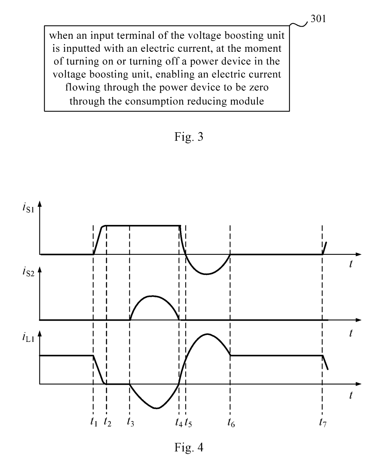
The present invention provides a power supply circuit and a power supply method. The power supply circuit comprises: a charge control unit, a battery and battery protection unit, a voltage stabilizing unit and a voltage boosting unit; the voltage boosting unit comprises: a consumption reducing module for, at the moment of turning on or turning off a power device in the voltage boosting unit, enabling an electric current flowing through the power device to be zero. The present invention, by arranging the consumption reducing module, enables an electric current flowing through the power device to be zero at the moment of turning on or turning off the power device in the voltage boosting unit, which realizes zero current turn-on or turn-off of the power device, and reduces consumption of the electric energy.

Description

RELATED APPLICATIONS[0001]The present application is the U.S. national phase entry of PCT / CN2015 / 087756 with an International filing date of Aug. 21, 2015, which claims the benefit of Chinese Application No. 201510166875.3, filed Apr. 9, 2015, the entire disclosures of which are incorporated herein by reference.FIELD OF THE INVENTION[0002]The present invention relates to the field of power supply technology, particularly to a power supply circuit and a power supply method.BACKGROUND OF THE INVENTION[0003]With the development of science and technology, electronic devices such as mobile phones and tablet computers have become indispensible things in people's life. However, the built-in batteries of these electronic devices have limited capacities, which may bring inconvenience to people's use sometimes. The mobile power supply as a portable charger has the advantages of having a small volume and being safe and reliable, and can charge the device at any time and any place.[0004]The mob...

Claims


Application Information

Patent Timeline
Patent Type & Authority Patents(United States)
IPC IPC(8): H02M3/158H02M3/335H02J7/00H02M1/42H02M3/156H02M1/00H02M1/34
CPCH02J7/0052H02J7/007H02J7/0093H02M3/156H02J7/0042H02J2007/0059Y02B70/1491H02M3/1588H02M3/335H02M2001/0058H02M2001/346Y02B40/90H02M3/158H02J2207/20H02J7/00711Y02B70/10H02M1/0058H02M1/346H02J7/00Y02B40/00
Inventor HAN, XIAOYANWANG, QINGMENGFANG, KUNKUN
Owner BOE TECH GRP CO LTD
Learn More