Distance measurement holder and machine tool having interfering object sensing function

a technology of distance measurement and object sensing, which is applied in the direction of instruments, manufacturing tools, metal-working machine components, etc., can solve the problems of increasing the number of parts and high failure rate, and achieve the effect of preventing the time required for the entire interference checking operation from increasing and reducing the calculation tim

Active Publication Date: 2014-12-11
FANUC LTD
View PDF4 Cites 14 Cited by
  • Summary
  • Abstract
  • Description
  • Claims
  • Application Information

AI Technical Summary

Benefits of technology

[0009]In the distance measurement holder according to the present invention, measurement equipment has a simple structure to allow a reduction in the number of parts. Accordingly, it is possible to keep the failure rate of the measurement equipment low. In addition, with regard to data used to sense an interfering object, whether or not the reflected beam is incident on a light receptor can be used as a trigger for distance calculation to allow construction of a system which performs processing at a high speed without image processing.
[0011]The machine tool having the function of sensing an interfering object when machining is performed therewith can reduce the calculation time for producing a program for an interference checking motion and prevent the time required for the entire interference checking operation from increasing.

Problems solved by technology

This causes a problem in ensuring a space in which such devices are to be placed or the problem of a higher failure rate resulting from an increased number of parts.

Method used


Image

  • Distance measurement holder and machine tool having interfering object sensing function
  • Distance measurement holder and machine tool having interfering object sensing function
  • Distance measurement holder and machine tool having interfering object sensing function

Examples


Embodiment Construction

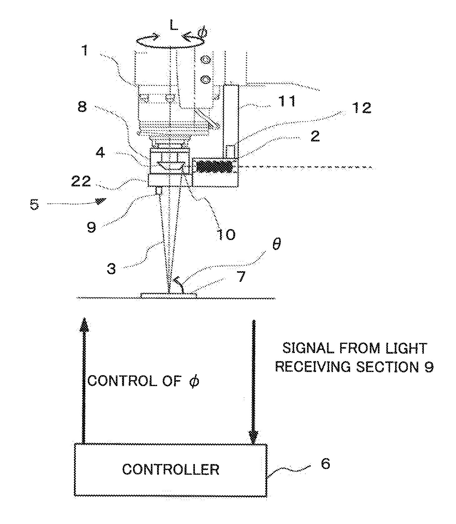
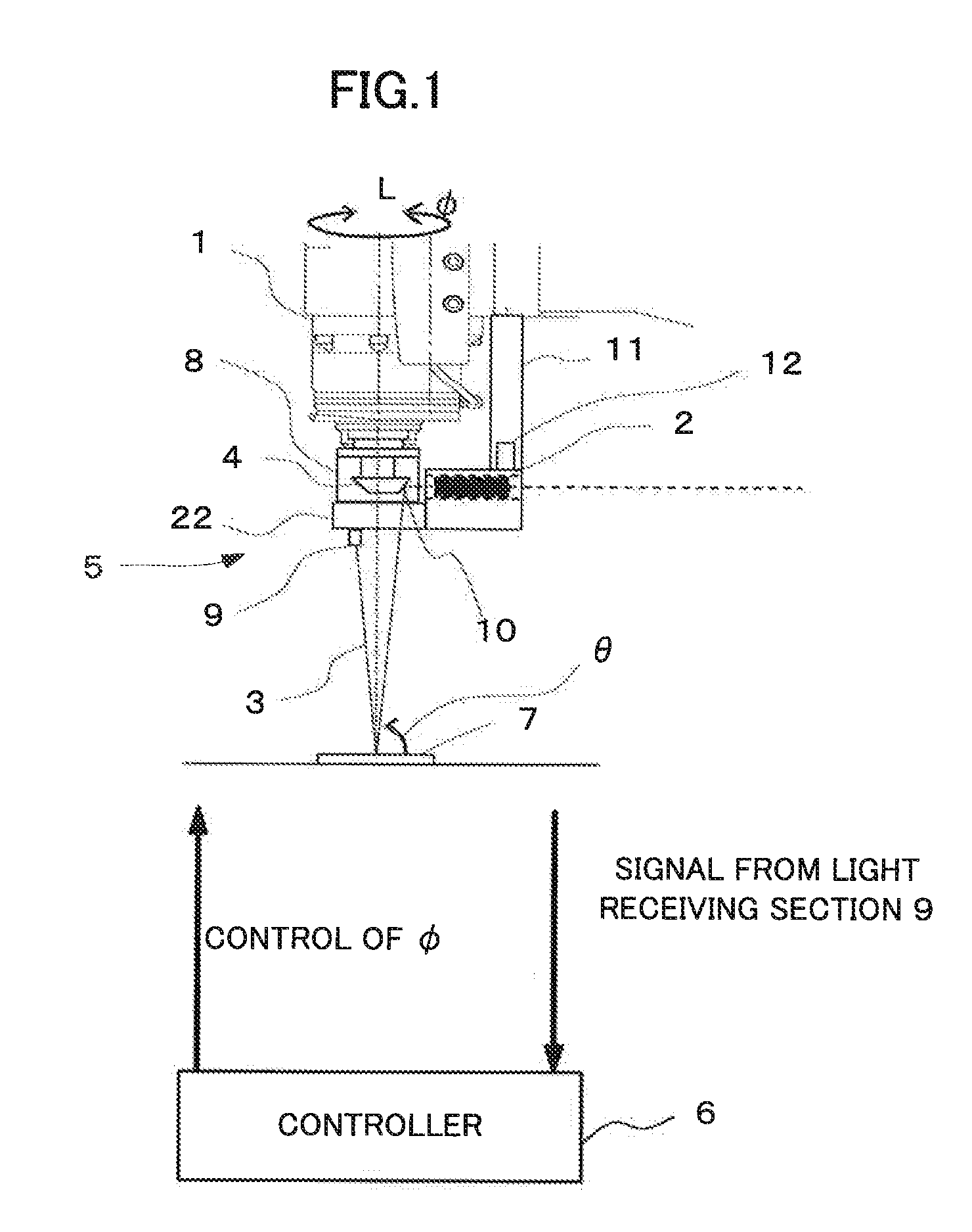
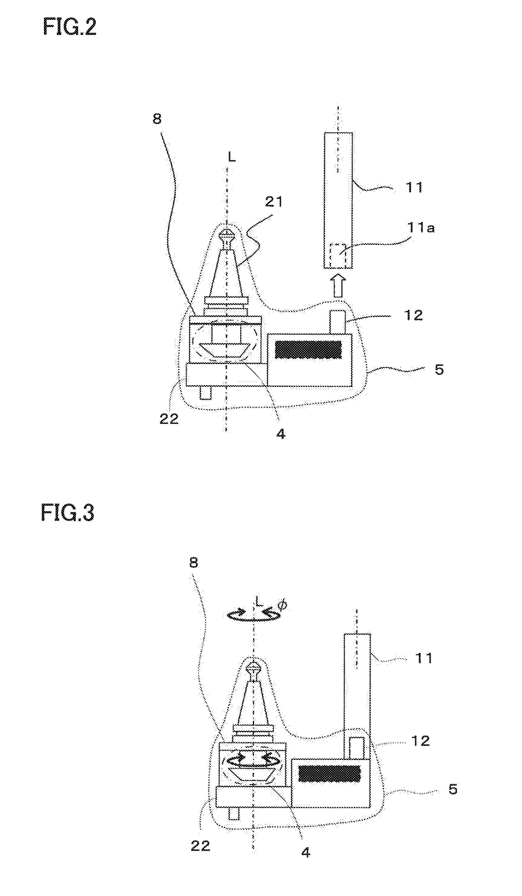
[0024]A structure of an embodiment of a distance measurement holder according to the present invention will be described with reference to FIGS. 1 to 3.

[0025]In a machine tool in which a main-shaft rotation angle φ around a rotation axis L of a main shaft 1 can be controlled, a distance measurement holder 5 is attached to the main shaft 1 to be used, as shown in FIG. 1.

[0026]The distance measurement holder 5 has a reflection mirror section 4 which relates an emission angle θ of a laser beam 3 emitted from a laser emission device 2 to the main-shaft rotation angle φ as a function thereof, i.e., tan θ=f(φ). The distance measurement holder 5 includes a holder non-rotating section 8 and the reflection mirror section 4. The laser emission device 2 is attached to the holder main body (holder non-rotating section 8).

[0027]The main-shaft rotation angle φ is controlled by a controller 6 in the machine tool to be gradually changed. The controller 6 in the machine tool references the main-shaf...


PUM


Abstract

A distance measurement holder is attached to the main shaft of a machine tool. A laser beam emitted from a holder main body is reflected by a reflection mirror section fixed to a tapered sleeve, and reflected by a measurement target, and then received by a light receiving section provided in the holder main body. The tapered sleeve is fit into the main shaft and supported to be rotatable relative to the holder main body. The distance measurement holder is shaped such that the angle of a side surface of the reflection mirror section changes in accordance with the rotation angle of the main shaft. The distance measurement holder thus configured determines the distance between the main shaft and the measurement target to determine whether or not a jig, a workpiece, the main shaft, and a cutting tool interfere with each other in the range of a rapid positioning motion specified in an NC program.

Description

BACKGROUND OF THE INVENTION[0001]1. Field of the Invention[0002]The present invention relates to a distance measurement holder and a machine tool having an interfering object sensing function.[0003]2. Description of the Related Art[0004]Conventionally, to prevent mutual interferences between a main shaft, a cutting tool, a workpiece, a jig, and the like resulting from a faulty operation or faulty judgment by a worker during a debugging operation for a machining program, a method has been devised which measures the positions or shapes of the workpiece and the jig in some way, compares information about the positions or shapes to the movement paths of the main shaft and the cutting tool to determine the presence or absence of an interference and stops a machining motion when it is determined that an interference occurs, thereby preventing the interference.[0005]A measurement method has been devised which involves no motion of elements such as a jig, a workpiece, a main shaft, a cuttin...

Claims


Application Information

Patent Timeline
Patent Type & Authority Applications(United States)
IPC IPC(8): G01B11/14
CPCG01B11/14B23Q17/2233B23Q17/2428B25H1/0092B25H1/10
Inventor YAMAMOTO, YASUYUKI
Owner FANUC LTD
Why Eureka
Try Eureka