
Knee brace with tool less length adjuster

a technology of knee braces and length adjusters, applied in the field of orthopaedic knee braces, can solve problems such as inadvertent release, and achieve the effect of improving the length adjustment mechanism

Active Publication Date: 2014-12-11
TOWNSEND IND INC
View PDF6 Cites 13 Cited by
  • Summary
  • Abstract
  • Description
  • Claims
  • Application Information

AI Technical Summary

Benefits of technology

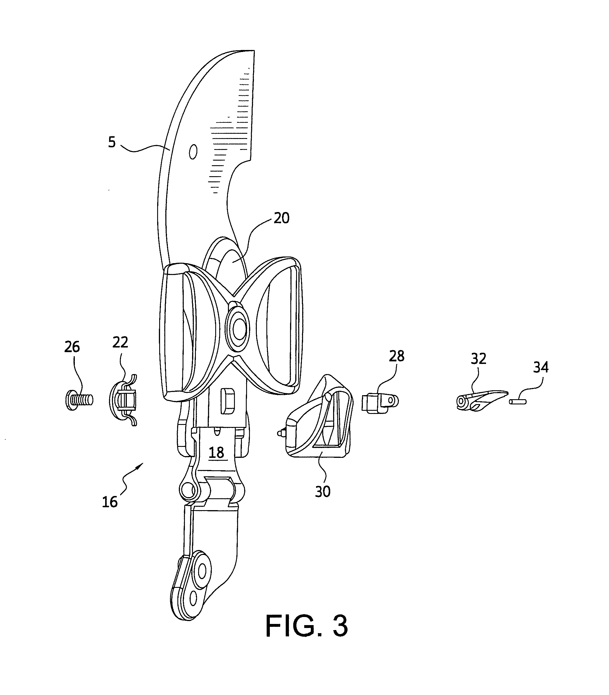
The patent is about improving adjustment mechanisms for knee braces. The new mechanism uses a circular detent plate and a lever to lock and release the adjustment. The lever pushes the detent plate to lock the knee brace, while releasing the lever allows the adjustment to happen. This mechanism is designed to be easy to use without tools and to prevent accidental adjustments.

Problems solved by technology

However, such a mechanism poses the disadvantage that contact of the button with an object, such as the leg of a table, can cause inadvertent release.

Method used


Image

  • Knee brace with tool less length adjuster
  • Knee brace with tool less length adjuster
  • Knee brace with tool less length adjuster

Examples


Embodiment Construction

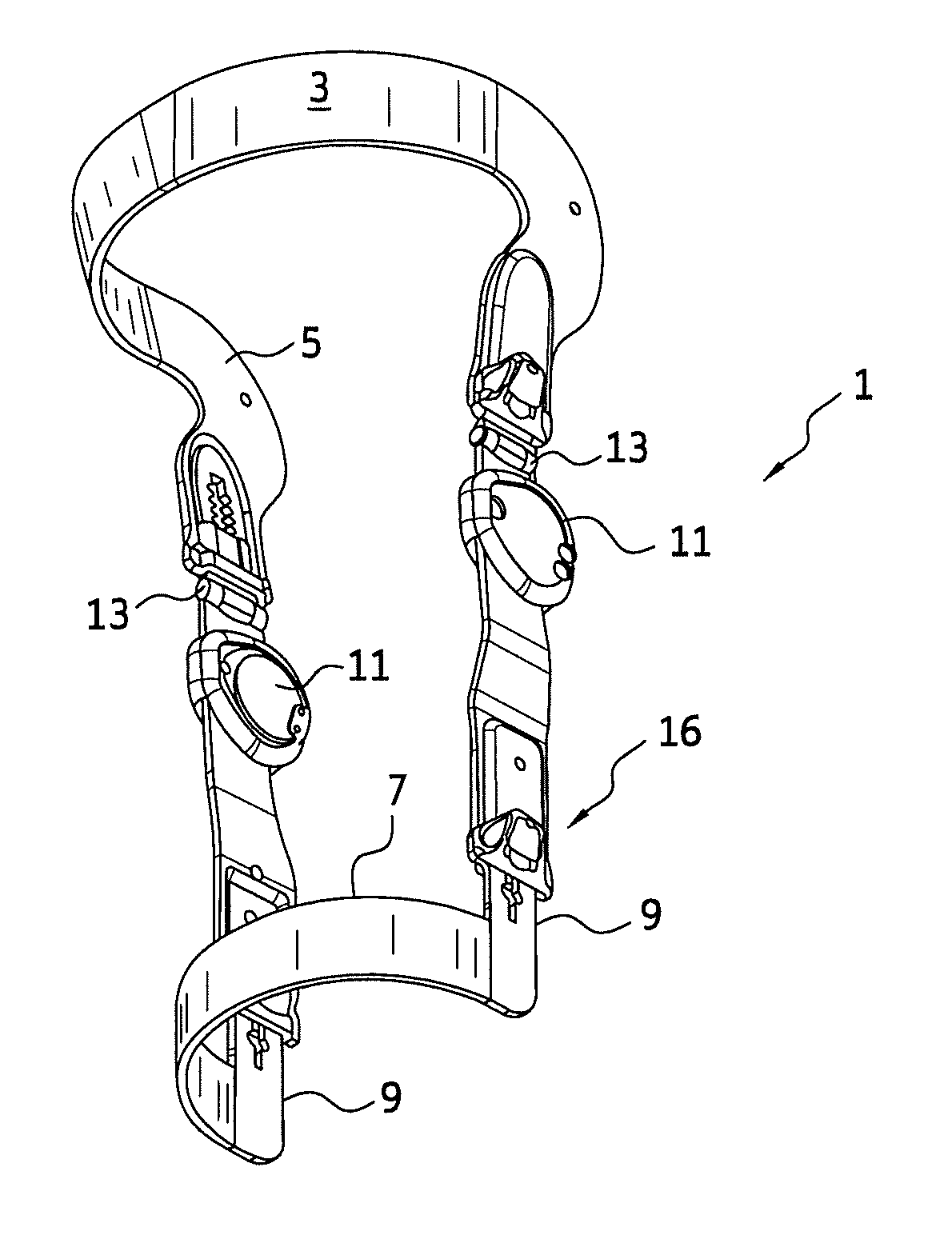
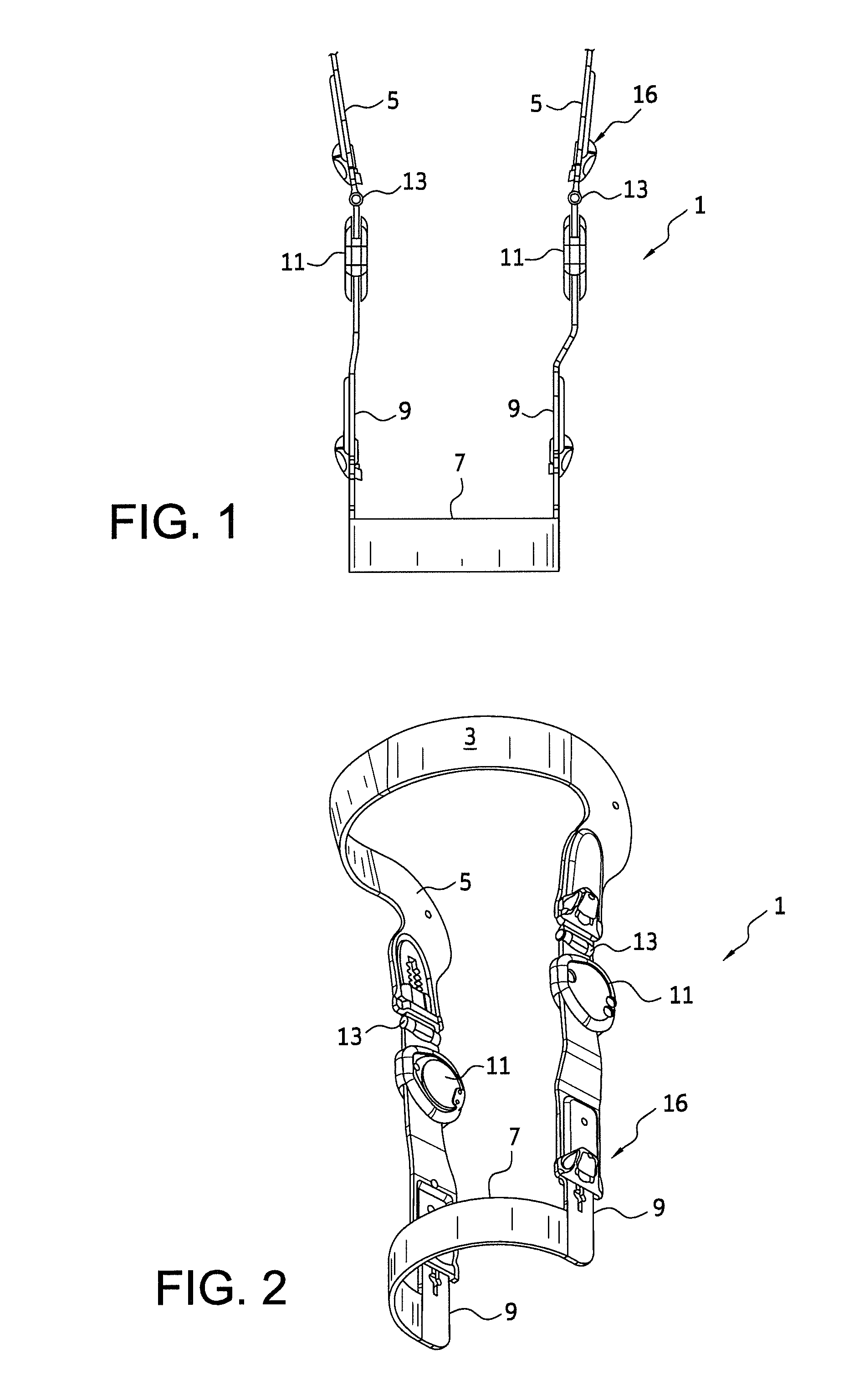
[0029]At the outset, it is noted that the orthotic knee brace shown in the drawings is merely an illustrative example and the following description of the invention should be viewed as applicable to numerous other types of knee braces, such as that of the above mentioned U.S. Pat. Nos. 6,981,957, 7,128,723 and 7,534,220. As can be seen in the drawings, as is typical, the knee brace 1 has an upper cross piece 3 connecting the medial and lateral femoral arms 5, a lower cross piece 7 connecting the medial and lateral tibial arms 9, and a polycentric hinge mechanism 11 connecting the lateral femoral and tibial arms and connecting the medial femoral and tibial arms. Furthermore, like U.S. Pat. No. 6,981,957, unicentric hinges 13 are disposed between the polycentric hinge mechanism and the femoral arm 5. Not shown are the upper and lower posterior straps that connect to medial and lateral sides of the cross pieces and / or medial and lateral femoral and tibial arms to hold the brace on the ...


PUM


Abstract

A knee brace which allows the same bolster pad to be used for either the right or left leg, is adjustable to compensate for the differing angle between men and women and allows individual adjustment for each patient's comfort and brace rotation for proper fit and joint alignment. These characteristics are obtained by a contoured bolster that is selectively mountable at various positions on either side of the shin cross piece depending on whether the brace is for the left or right leg, the bolster always being on the medial side of the shin to contact the flat section on the front of the shin thereby minimizing unwanted rotation of the brace. The bolster pad has a front face with a curvature matched to a curvature of an inner side of the cross piece and a flat on a rear side to contact the front of the shin.

Description

CROSS REFERENCE TO RELATED APPLICATION[0001]This application is a non-provisional conversion of provisional application 61 / 565,572.BACKGROUND OF THE INVENTION[0002]1. Field of the Invention[0003]The present invention relates to orthopedic knee braces of the type in which at least one of the femoral arms has a length adjustment mechanism; and wherein adjustment of the length of at least one of the arms produces a medial-lateral angular movement of at least one or the other of the femoral arms.[0004]2. Description of Related Art[0005]An orthopedic knee braces of the type to which the present invention is directed is known from U.S. Pat. No. 6,981,957 of which the present inventor is a co-inventor. The length adjustment mechanism of this knee brace comprises a slide mechanism on at least one of the femoral arms which is in the form of a slotted guide and a slider which is fixable at selected locations along the length of said slotted guide by a screw that extends through the slot of th...

Claims


Application Information

Patent Timeline
Patent Type & Authority Applications(United States)
IPC IPC(8): A61F5/01
CPCA61F2005/0155A61F5/0125A61F5/0123A61F2005/0134A61F2005/0148
Inventor KNECHT, STEVEN S.
Owner TOWNSEND IND INC
Learn More