Filter box assembly and filter unit

a filter box and filter technology, applied in the field of filter box assembly, can solve the problems of increased bulk and weight of the device, disadvantageous increase in bulk and weight, and extreme discomfort in use, and achieve the effect of enhancing the performance of the particulate filter and increasing efficiency

Active Publication Date: 2014-12-18
HOWIE ROBIN MIDDLEMASS +1
View PDF1 Cites 3 Cited by
  • Summary
  • Abstract
  • Description
  • Claims
  • Application Information

AI Technical Summary

Benefits of technology

[0067]Therefore, in one aspect the present invention describes a novel technique for the manufacture of filters (filter box assemblies) for use in (personal) respiratory protective equipment, said filter box assemblies having low airflow resistance.
[0075]Where the particulate filter medium is formed from electrostatically charged fibres, compression of the particulate filter can increase the efficiency with which the filter collects particulates, so enhancing the performance of the particulate filter.
[0108]Therefore, in one aspect, the invention describes a means by which single or double-sided filter units comprising gas (vapour) and particulate filters can be manufactured reliably, and where the particulate filter has been compressed to form a “spring” which locks the adsorbents / absorbents (i.e., the gas filter layer) in place.

Problems solved by technology

However, in such situations many users find that the breathing resistance of the devices makes them extremely uncomfortable to use, to the extent that some would-be users refuse to wear such equipment.
If users consider the devices to be too uncomfortable, they may refuse to wear them or they may wear the devices incorrectly in an attempt to minimise discomfort.
Although devices with large or multiple filters will have a lower breathing resistance than devices fitted with single filters of normal size, the use of larger or multiple filters increases the bulk and weight of the devices.
Such increased bulk and weight is disadvantageous, particularly for devices which must be carried on the body, or stored in large numbers close to sites of potential use.
However, although technically effective, such double-sided filters can be awkward to manufacture to the required standards of quality; particularly if the gas and vapour filter beds are of shallow depth, e.g. of less than about 10 mm depth.
This makes such filters difficult to manufacture and, inevitably, adds to the overall bulk.

Method used


Image

  • Filter box assembly and filter unit
  • Filter box assembly and filter unit
  • Filter box assembly and filter unit

Examples


Embodiment Construction

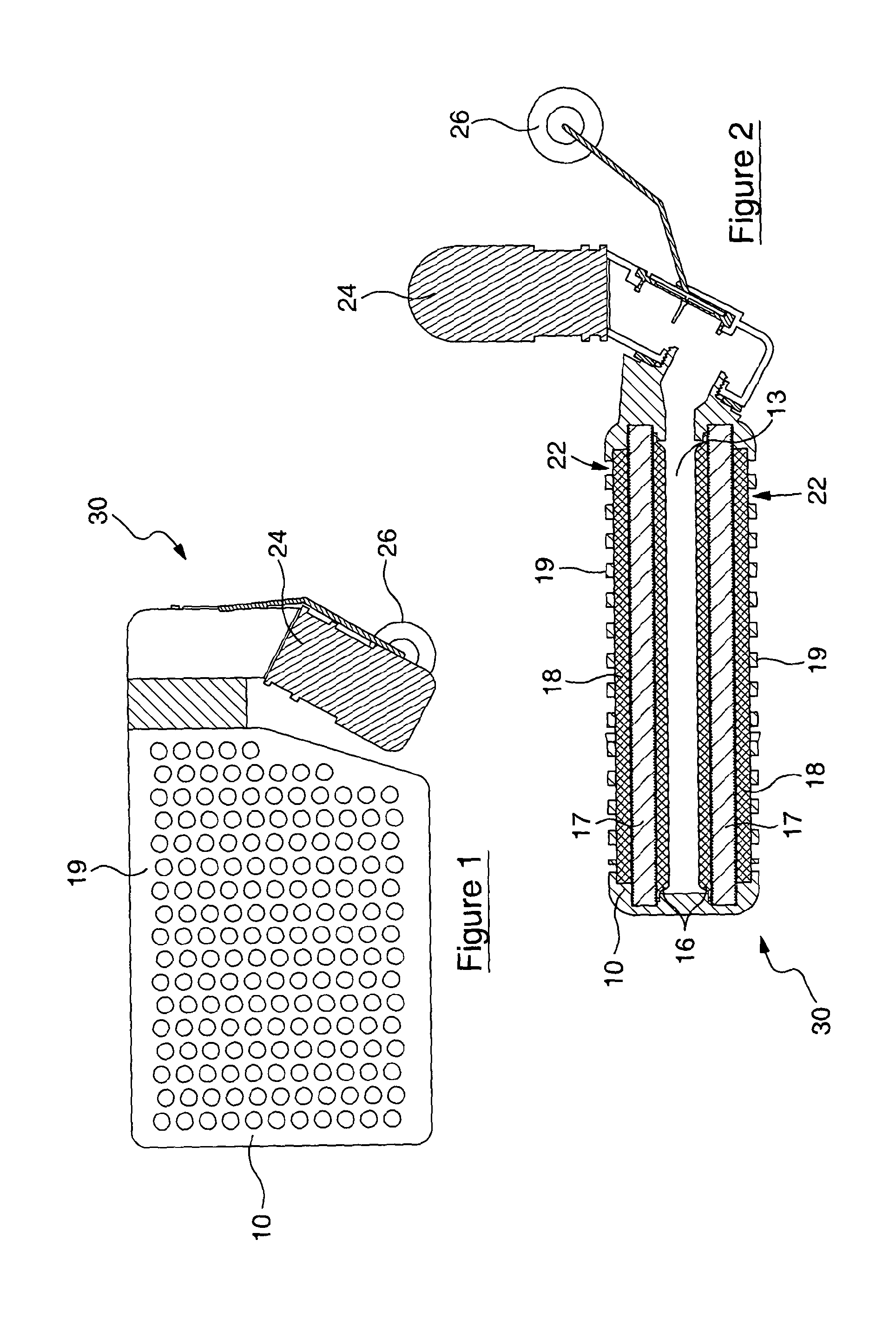
[0115]Referring to FIG. 1, there is shown a respiratory protective device 30 having a filter box assembly 10 connected to a mouthpiece 24. Also shown are a perforated filter plate 19 and a nose clip 26.

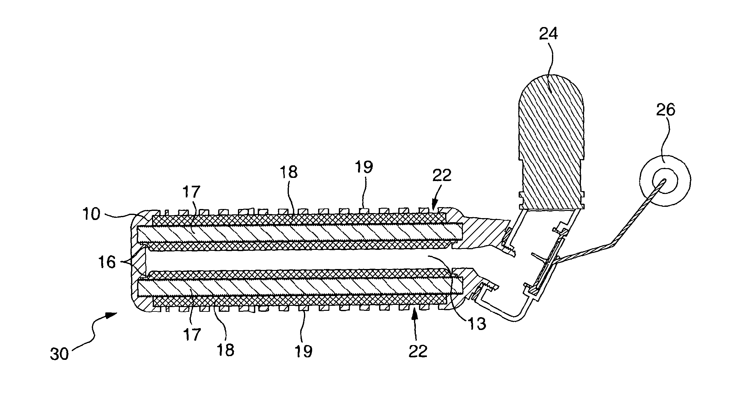
[0116]Referring now to FIG. 2, there is shown there is shown a respiratory protective device 30 having a filter box assembly 10 connected to a mouthpiece 24. The filter box assembly contains two filter units 22 which share a common air channel 13. As can be seen, the air channel 13 is in direct contact with the filter units 22, and in this case is in direct contact with a support scrim (support layer) 16, which is a particulate filter. Adjacent the support scrim 16 is a gas filter layer 17, and adjacent the gas filter layer 17 is a particulate filter later 18. To the outside of the assembly 10 is a perforated filter plate 19 which is adjacent the particulate filter layer 18. Also shown is a nose clip 26.

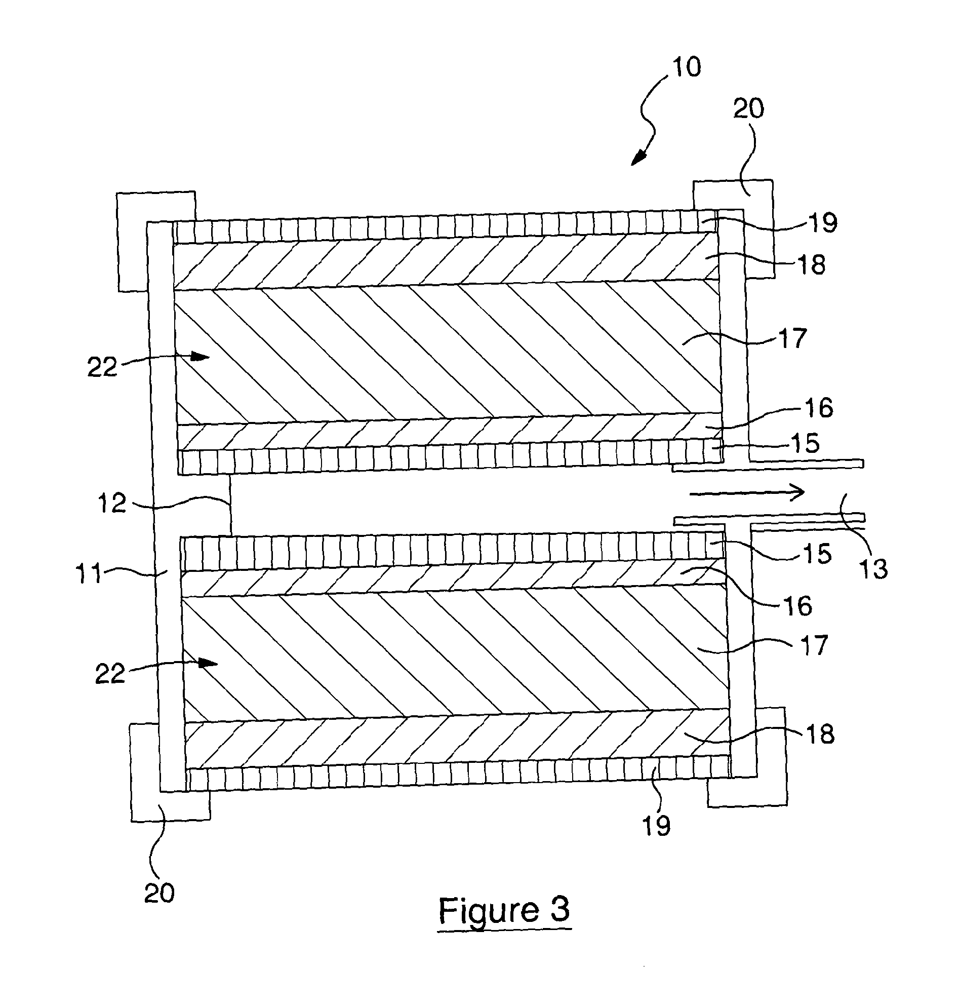
[0117]In this embodiment, the filter unit 22 comprises the support scrim (support ...


PUM

PropertyMeasurementUnit
depthaaaaaaaaaa
forceaaaaaaaaaa
depthaaaaaaaaaa

Abstract

A filter unit for use in a filter box assembly, the filter unit comprising a particulate filter layer and a gas filter layer, the particulate filter layer being configured to bias towards the gas filter layer, exerting pressure thereon. There is also described filter box assemblies (including a duel filter assembly) comprising the filter unit, and a respiratory protective device comprising the filter unit. Also described is a method of manufacturing a filter unit with a gas filter layer and a particulate filter layer, wherein a force is applied to the particulate filter layer causing it to fix the gas filter layer in place. Also described is a method of manufacturing a dual filter assembly wherein a casing is twice reversibly attached to and detached from a support surface, filter units being added to the casing when the casing is attached to the surface.

Description

FIELD OF THE INVENTION[0001]The present invention relates generally to a filter box assembly and a method of manufacture thereof, and in particular to filter box assembly for use with or in a respiratory protective device. In one aspect the present invention relates to a filter unit and a method of manufacture thereof, and in particular to a filter unit for use with or in a filter box assembly.BACKGROUND OF THE INVENTION[0002]A number of respiratory protective devices are fitted with filter box assemblies and / or filter units. The filter box assemblies and / or filter units are ordinarily connected to a facepiece, such as a half-mask or a mouthpiece, which provides an effectively airtight connection between the breathing zone or mouth of the wearer of the device and the filter box assembly / filter unit. This ensures that the user can only breathe air which has been filtered to remove contaminants including, for example, toxic gases and particulates.[0003]As noted above, respiratory prot...

Claims


Application Information

Patent Timeline
Patent Type & Authority Applications(United States)
IPC IPC(8): A62B23/02B01D53/04
CPCB01D53/0415A62B23/02B01D46/0015B01D46/0032B01D46/0036B01D46/0091B01D46/10B01D2253/102B01D2257/93B01D2259/4541B01D2259/4583B01D2265/028B01D2267/30A62B7/10A62B19/00A61M16/105B01D2253/106B01D2253/108B01D2253/116B01D2257/90B01D2258/06A61M16/0825A61M16/107Y10T29/49826B01D46/645B01D46/58
Inventor HOWIE, ROBIN MIDDLEMASSROBINSON, DEREK MERVYN
Owner HOWIE ROBIN MIDDLEMASS
Why Eureka
Try Eureka