Keyswitch structure

a keyswitch and structure technology, applied in the field of keyswitch structure, can solve the problems of reducing the size of the conventional keyswitch structure to reach the ultimate limit, and the assembly is difficult, and achieves the effect of stable up-and-down movement and easy assembly

Inactive Publication Date: 2014-12-18
DARFON ELECTRONICS (SUZHOU) CO LTD +1
View PDF2 Cites 7 Cited by
  • Summary
  • Abstract
  • Description
  • Claims
  • Application Information

AI Technical Summary

Benefits of technology

[0006]An objective of the invention is to provide a keyswitch structure, which provides stable up-and-down movement and is easy to assemble.

Problems solved by technology

However, as demands for lightness and thinness become higher, the reduction in size to the conventional keyswitch structure reaches an ultimate limitation due to the dimension of the resilient part and the scissors supporting mechanism.
Furthermore, when assembling the scissors supporting mechanism in the conventional keyswitch, four bearing ends of the scissors supporting mechanism need to be connected to the keycap and baseplate respectively, leading to much difficulty to the assembly.

Method used


Image

  • Keyswitch structure
  • Keyswitch structure
  • Keyswitch structure

Examples


Embodiment Construction

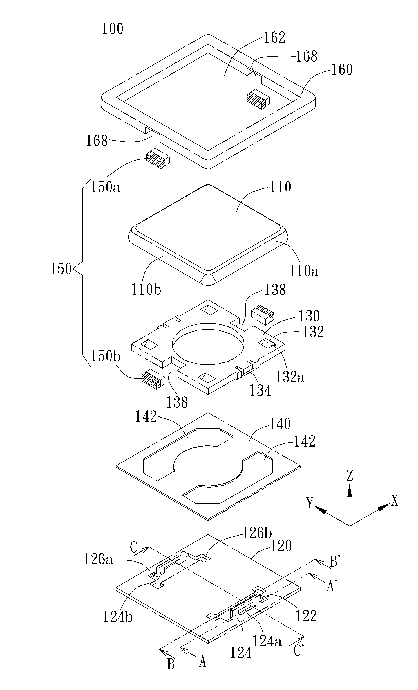
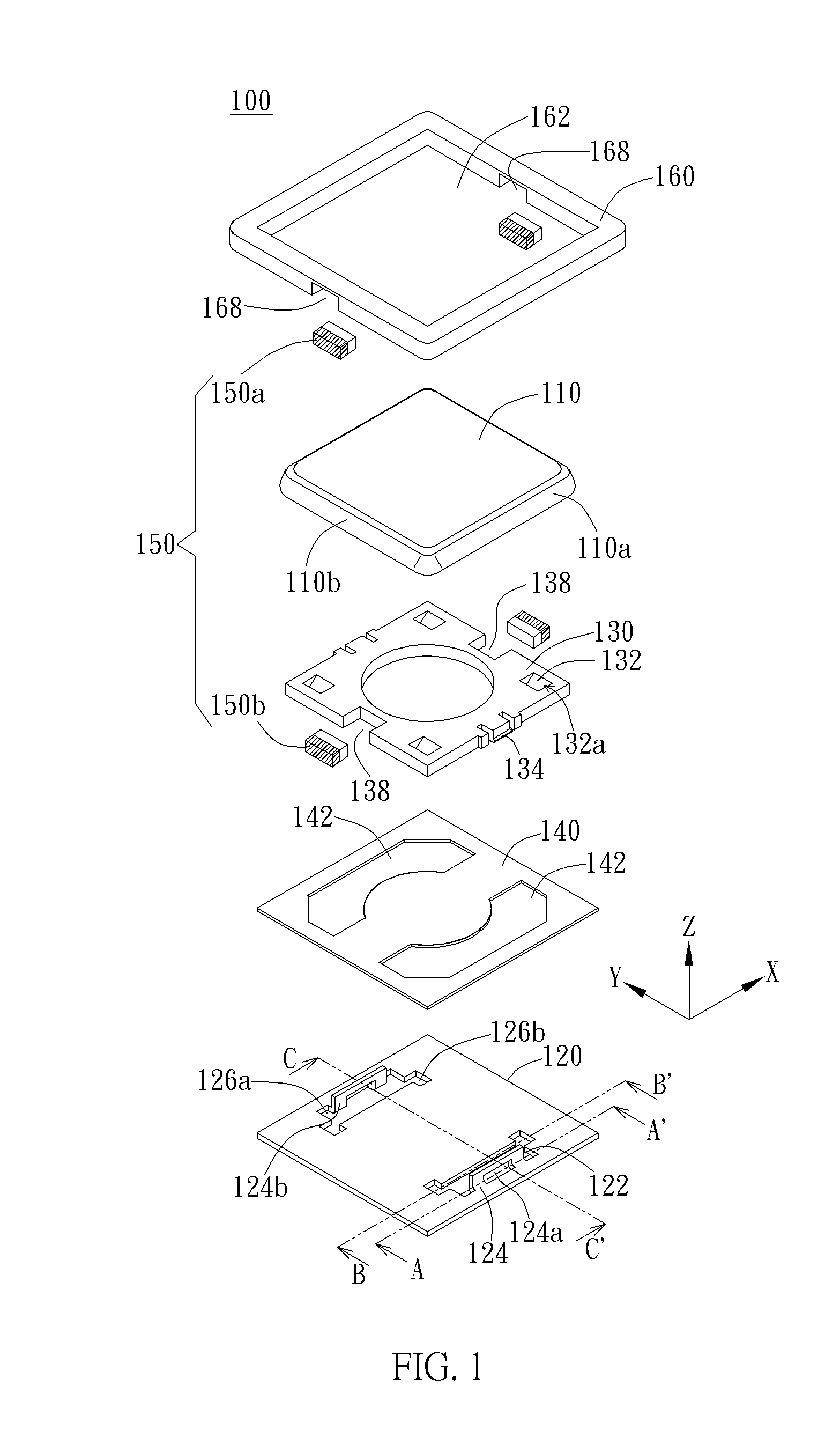
[0029]The invention provides a keyswitch structure capable of being applied to any press input device such as keyboard, reduces the height of keys of the keyswitch structure effectively, simplifies the assembly complexity of the keyswitch structure, and can satisfy user's pressing habits. Referring to the figures, the following will describe structure and operation of components of the keyswitch structure of the invention in detail.

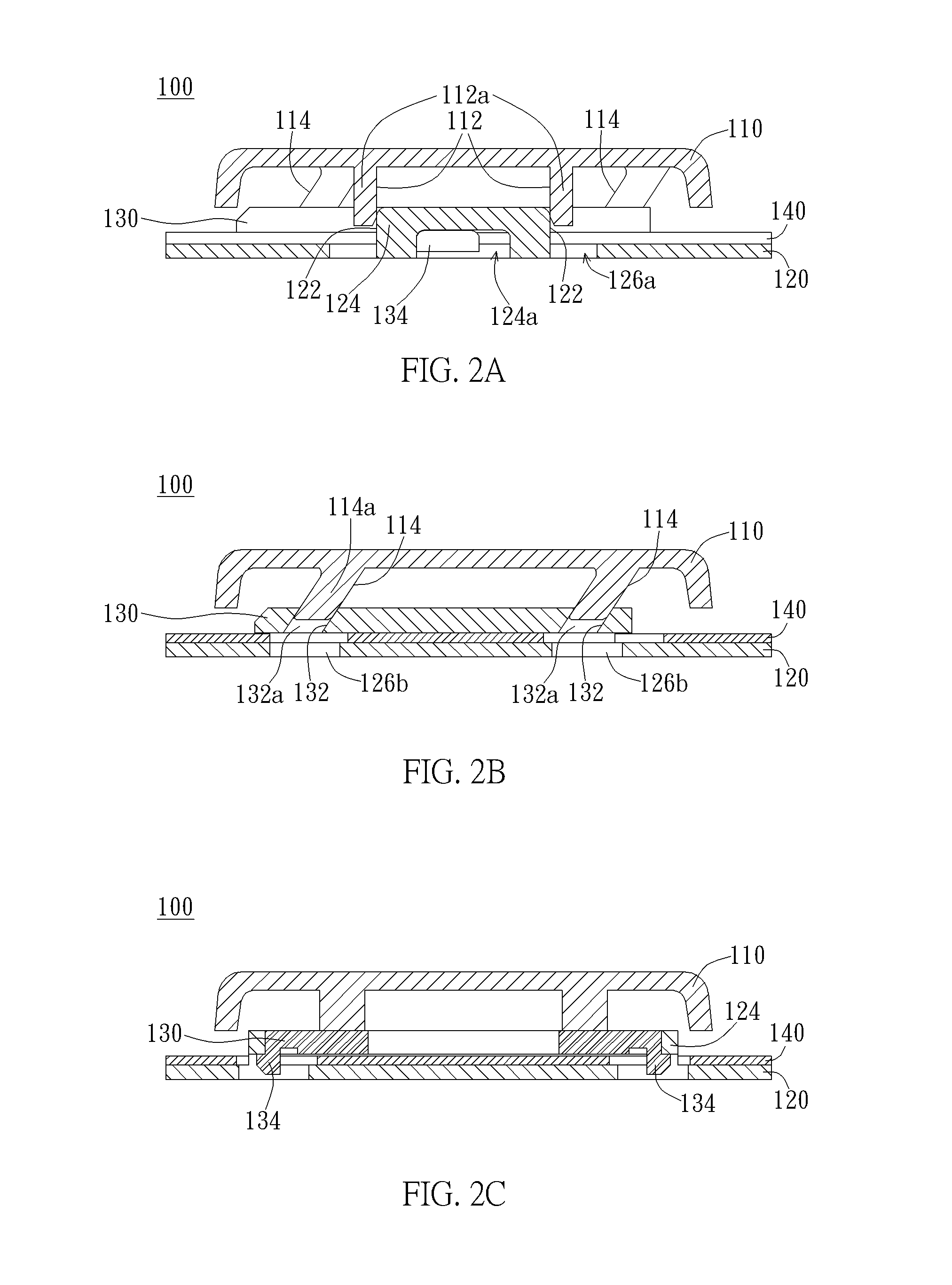
[0030]FIG. 1 is an exploded view of a keyswitch structure of the invention. FIG. 2A is a sectional view of the keyswitch structure after assembled along the line A-A′ in FIG. 1. FIG. 2B is a sectional view of the keyswitch structure after assembled along the line B-B′ in FIG. 1. FIG. 2C is a sectional view of the keyswitch structure after assembled along the line C-C′ in FIG. 1. As shown by FIG. 1 and FIGS. 2A-2C, the keyswitch structure 100 of the invention includes a keycap 110, a baseplate 120, a slidable part 130, a switch layer 140, and a restoring m...


PUM


Abstract

A keyswitch structure includes a keycap having a vertical connection member and a vertical-horizontal-translation mechanism, a baseplate having a vertical connection member, a slidable part having a vertical-horizontal-translation mechanism, and a restoring member. The vertical connection members are engaged for constraining the keycap to move relative to the baseplate substantially along a Z axis. The vertical-horizontal-translation mechanisms are engaged, so that the slidable part can perform a motion in response to a movement of the keycap toward the baseplate along the Z axis upon a pressing operation. The motion includes a displacement in a first direction. When the pressing operation is discontinued, a horizontal restoring force by the restoring member enables the slidable part to perform a motion that includes a displacement in a second direction to move the keycap away from the baseplate along the Z axis. The second direction is opposite to the first direction.

Description

BACKGROUND OF THE INVENTION[0001]1. Field of the Invention[0002]The invention relates to a keyswitch structure, and especially relates to a keyswitch structure, of which a keycap moves vertically along a Z axis, of which a guiding part disposed underneath the keycap. The guiding part slides toward (1) a first direction in response to a downward movement of the keycap, and (2) a direction opposite to the first direction in response to a horizontal restoring force.[0003]2. Description of the Prior Art[0004]A conventional keyswitch structure usually uses a resilient part to provide a restoring force to drive a keycap to move upward after a pressing thereon is discontinued, and also uses a scissors supporting mechanism to provide a necessary lift stability to the keycap. However, as demands for lightness and thinness become higher, the reduction in size to the conventional keyswitch structure reaches an ultimate limitation due to the dimension of the resilient part and the scissors supp...

Claims


Application Information

Patent Timeline
Patent Type & Authority Applications(United States)
IPC IPC(8): H01H13/02
CPCH01H13/02H01H13/705H01H2221/026H01H2221/04H01H2227/036
Inventor CHIANG, TZU-PANG
Owner DARFON ELECTRONICS (SUZHOU) CO LTD
Why Eureka
Try Eureka