Eureka AIR delivers breakthrough ideas for toughest innovation challenges, trusted by R&D personnel around the world.

High precision DC to DC converter with wide load range and gate drive circuit for use therein

Active Publication Date: 2014-12-18
KOREA ELECTROTECH RES INST
View PDF4 Cites 14 Cited by
  • Summary
  • Abstract
  • Description
  • Claims
  • Application Information

AI Technical Summary

Benefits of technology

The present invention provides a DC / DC converter that can be used in all load ranges, from no load to full load, while maintaining low conduction loss and switching loss. Additionally, it can minimize ripple components in the output voltage and protect sensitive loads from arcs. In one aspect, the invention includes an isolated resonant converter with high precision and can control the output voltage with high accuracy and reduce ripples without increasing the value of filter capacitor.

Problems solved by technology

However, when the switching frequency becomes higher, a switching loss of the resonant converter increases.
That is, in the DC / DC resonant converter operation in the continuous conduction region, the IGBT loss rapidly increases during the light load operation, and thus, the efficiency can be rapidly reduced or the switching element such as the IGBT can be damaged by burning.

Method used


Image

  • High precision DC to DC converter with wide load range and gate drive circuit for use therein
  • High precision DC to DC converter with wide load range and gate drive circuit for use therein
  • High precision DC to DC converter with wide load range and gate drive circuit for use therein

Examples


Embodiment Construction

[0076]Hereinafter reference will now be made in detail to various embodiments of the present invention, examples of which are illustrated in the accompanying drawings and described below. While the invention will be described in conjunction with exemplary embodiments, it will be understood that present description is not intended to limit the invention to those exemplary embodiments. On the contrary, the invention is intended to cover not only the exemplary embodiments, but also various alternatives, modifications, equivalents and other embodiments, which may be included within the spirit and scope of the invention as defined by the appended claims.

[0077]The above and other features of the invention are discussed infra.

[0078]Hereinafter, exemplary embodiments of the present invention will be described in detail with reference to the accompanying drawings so that those skilled in the art can easily carry out the present invention.

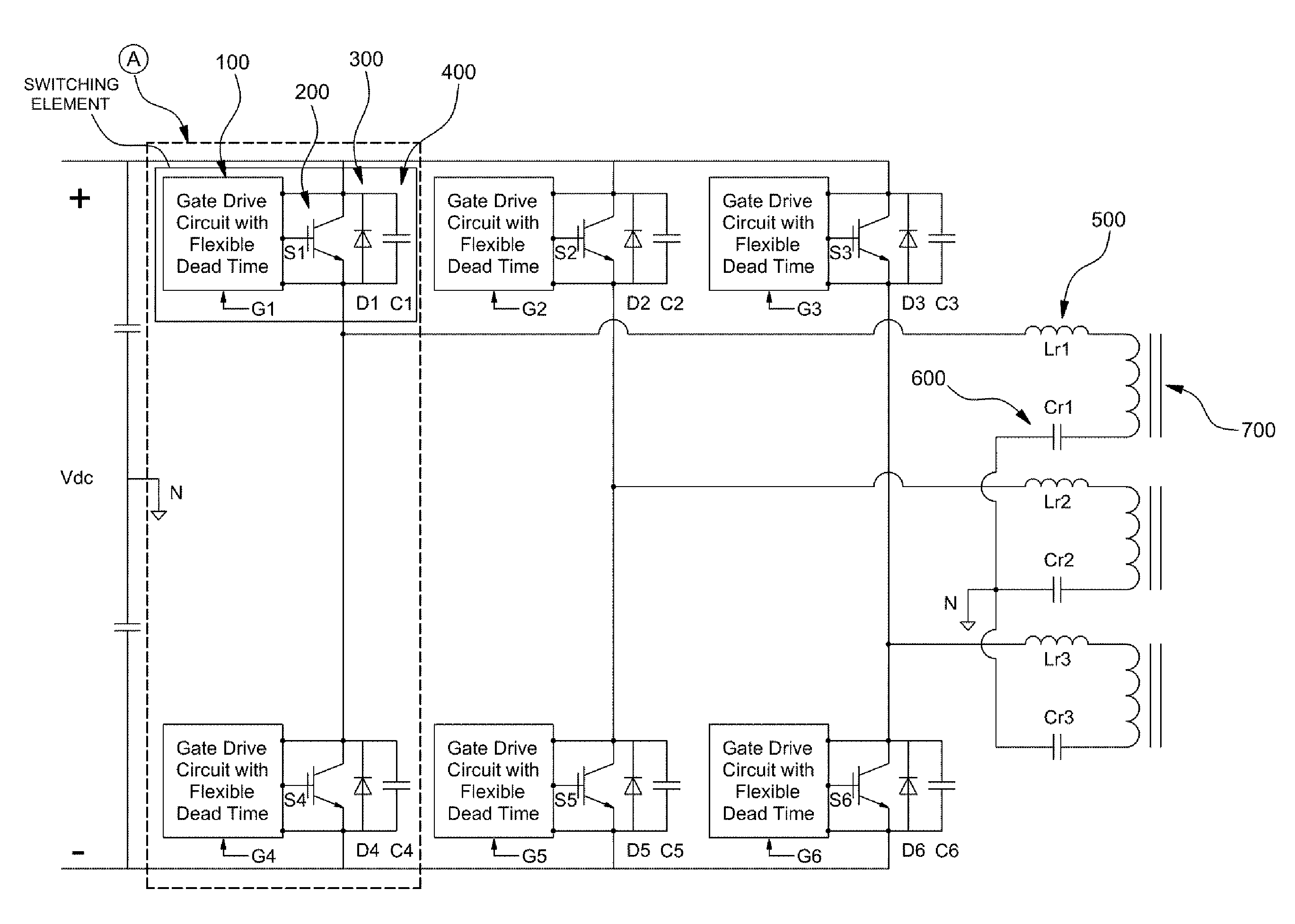
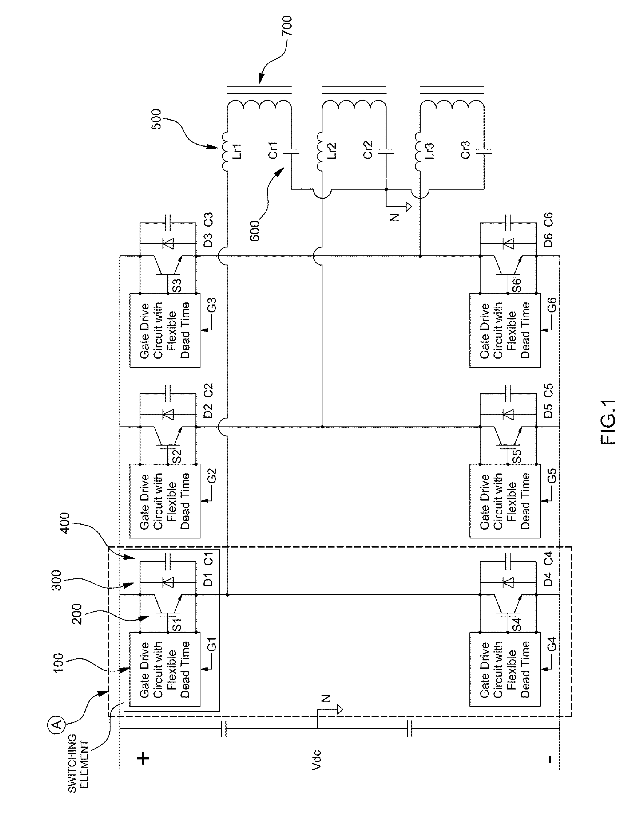
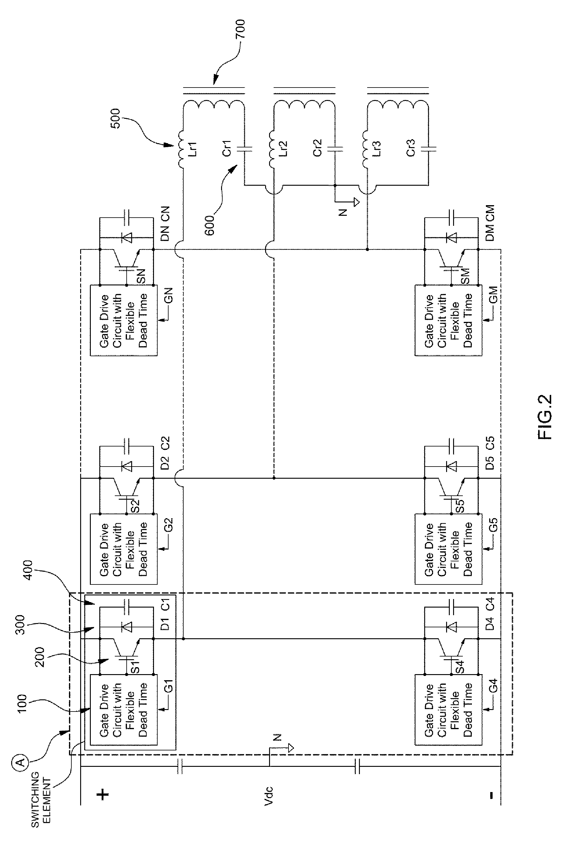
[0079]FIG. 1 is a view illustrating an internal config...


PUM


Abstract

A high precision DC / DC resonant converter with a wide load range includes a first switch leg having one end connected to an anode terminal of a DC power source and the other connected to a cathode terminal of the DC power source to independently operate at a switching frequency used in an application of an output voltage for no load or a light load equal to or less than a rated load; and one or more second switch legs having one end connected to the anode terminal of the DC power source and the other end connected to the cathode terminal of the DC power source to operate at a switching frequency for the rated load or a frequency equal to or less than the switching frequency used in the application of the output voltage for no load or the light load that the first switch leg takes charge of.

Description

CROSS-REFERENCE TO RELATED APPLICATION[0001]This application claims under 35 U.S.C. §119(a) the benefit of Korean Patent Application No. 10-2013-0068148 filed Jun. 14, 2013, the entire contents of which are incorporated herein by reference.BACKGROUND[0002](a) Technical Field[0003]The present invention relates to a resonant converter. More particularly, the present invention relates to a resonant converter that enables high efficient precision control even at no load or light load in which low power is used.[0004](b) Background Art[0005]Generally, DC / DC converters have been widely used in various industrial fields to convert an input DC voltage into an output DC voltage at a different level. The DC / DC converter converts a DC voltage into an AC voltage, and then the AC voltage is either raised or dropped by a transformer to be rectified again into a DC voltage, allowing the voltage to be transformed.[0006]There are many circuit configurations for implementing the DC / DC converter, and ...

Claims


Application Information

Patent Timeline
IPC IPC(8): H02M3/158
CPCH02M2003/1586H02M3/1584H02M3/285H02M3/33523Y02B70/10H02M3/00H02M3/22H02M3/24H02M3/28H02M3/1586
Inventor RYOO, HONG JEJANG, SUNG ROCAN, SUK HOGONG, JI WOONG
Owner KOREA ELECTROTECH RES INST
Why Eureka
Eureka Blog
Learn More