Image pickup apparatus, method of controlling image pickup apparatus, image pickup apparatus system, and image pickup control program stored in storage medium of image pickup apparatus
a technology of image pickup and control program, which is applied in the field of image pickup apparatus, can solve problems such as difficulty in understanding which control is to be performed by which operation
- Summary
- Abstract
- Description
- Claims
- Application Information
AI Technical Summary
Benefits of technology
Problems solved by technology
Method used
Image
Examples
first embodiment
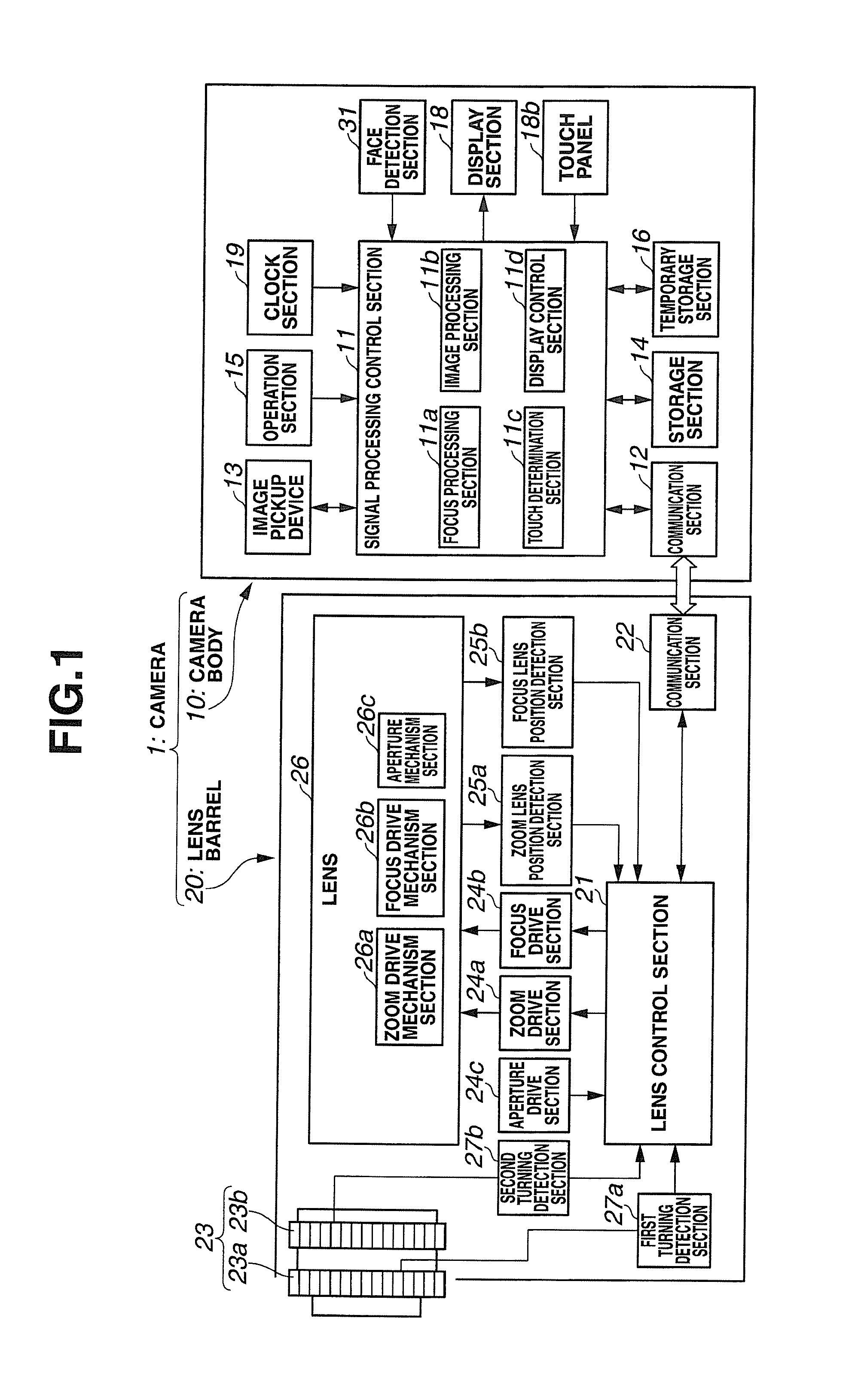
[0049]A schematic configuration of an image pickup apparatus of a first embodiment of the present invention (hereafter, merely referred to as a camera) will be first described. FIG. 1 is a block configuration diagram showing a schema of a primary internal configuration of an image pickup apparatus (camera) of a first embodiment of the present invention.
[0050]A camera 1 of the present embodiment is constituted by, as shown in FIG. 1, a camera body 10 and a lens barrel 20. The camera 1 is a so-called interchangeable lens camera in which the lens barrel 20 is configured to be detachable with respect to the camera body 10. Although, in the present embodiment, an interchangeable lens camera is described by way of an example as an image pickup apparatus, cameras as image pickup apparatuses to which the present invention can be applied are not limited to this form, and the present invention can be applied similarly, for example, fixed lens cameras of a form in which the camera body 10 and ...
second embodiment
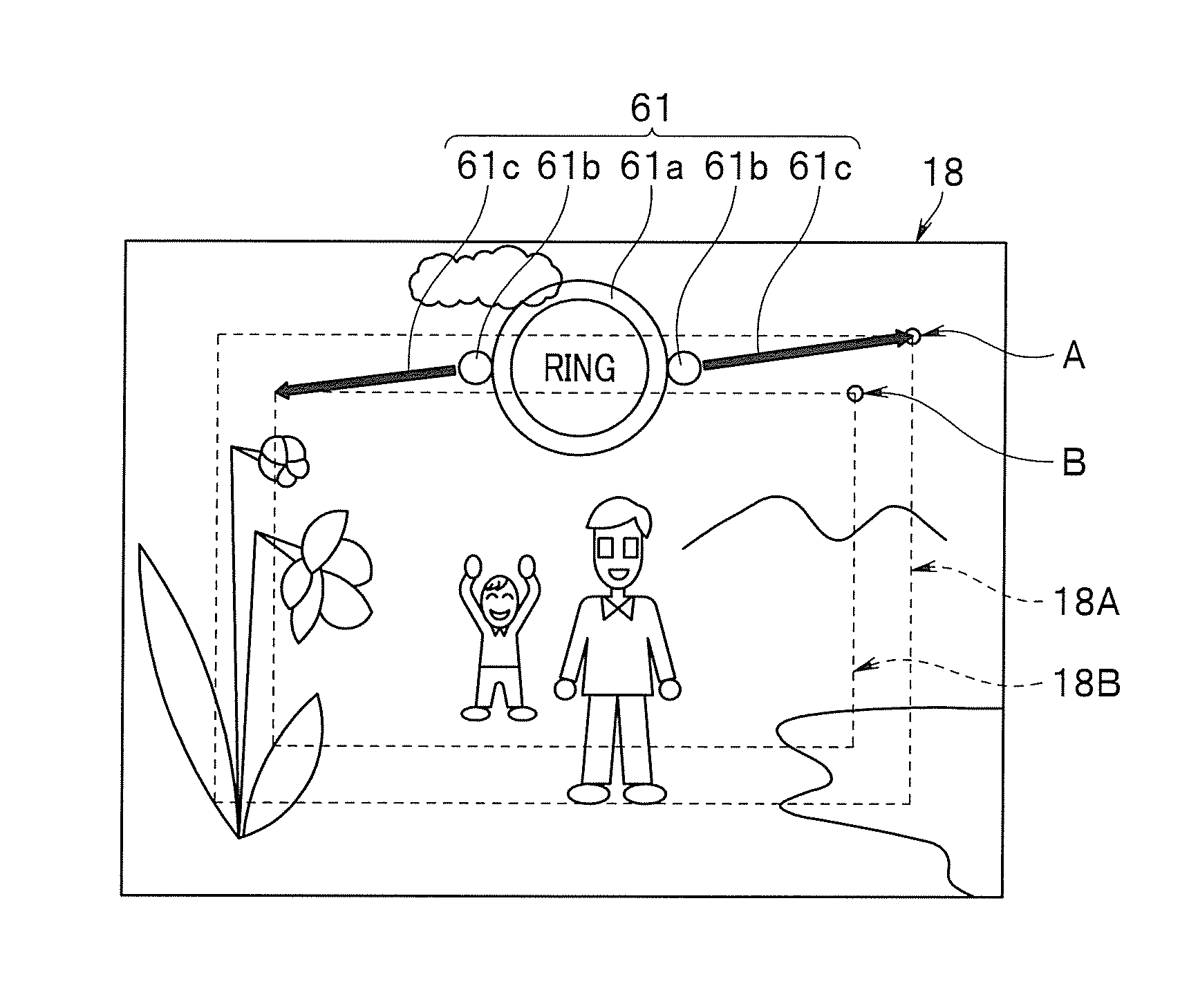
[0151]A second embodiment of the present invention to be next described illustrates an example in which a display pattern in the fine zoom adjustment mode is different from that of the abovementioned first embodiment. A basic configuration of an image pickup apparatus (camera) itself of the present embodiment is substantially similar to that of the abovementioned first embodiment, and only a camera control sequence slightly differs from that of the abovementioned first embodiment. Therefore, with respect to components similar to those of the abovementioned first embodiment, illustration will be omitted and description will be made with the same reference characters. In addition, with respect to a similar processing sequence, illustration and description thereof will be omitted, and only different parts thereof will be described below.
[0152]FIG. 8 is a flowchart showing a camera control processing sequence in the image pickup apparatus (camera) of the second embodiment of the present...
third embodiment
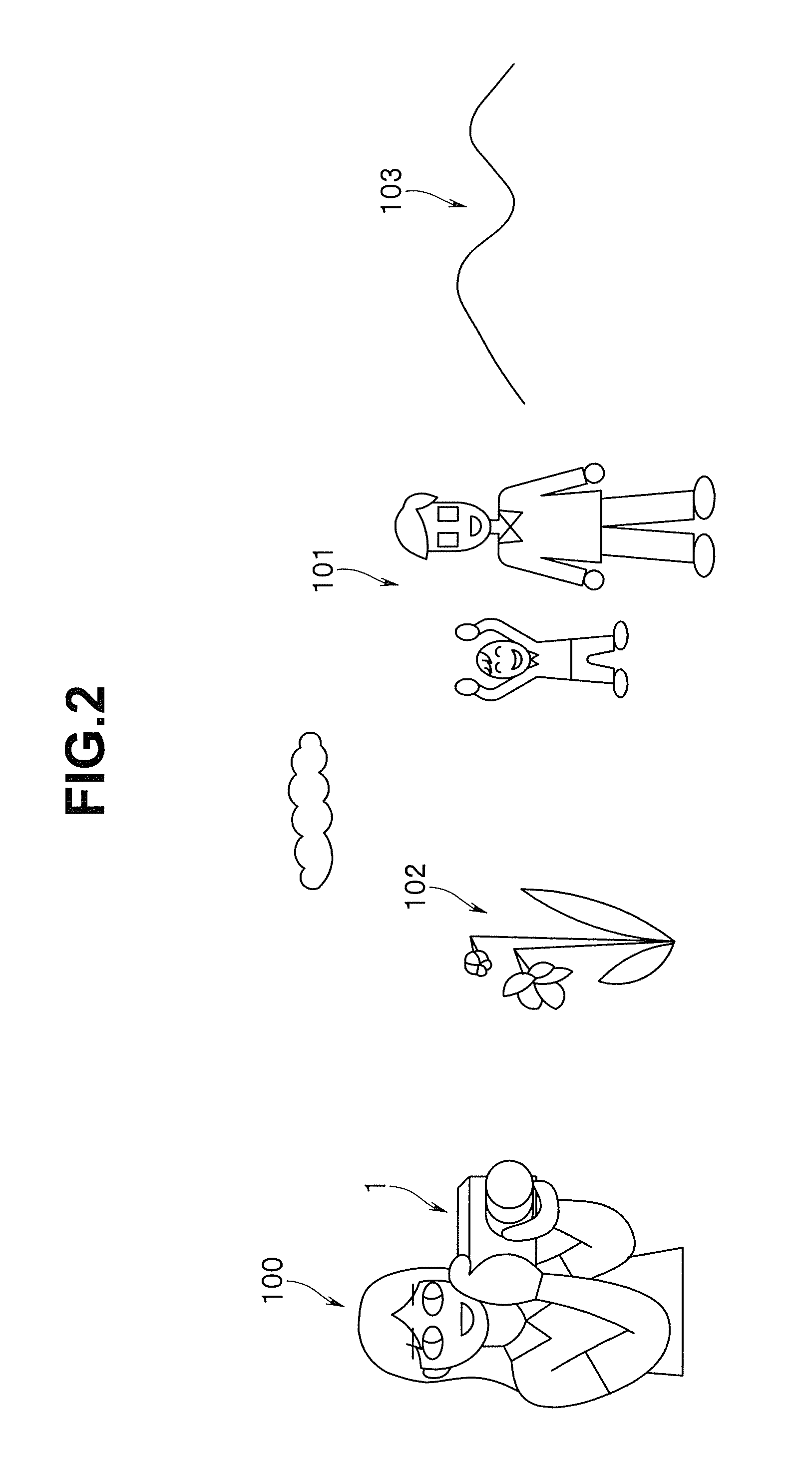
[0200]A third embodiment of the present invention will be next described. The present embodiment illustrates an example of one form of focusing control that is applied to an image pickup apparatus (camera) having a configuration substantially similar to the respective abovementioned embodiments. Therefore, a basic configuration of an image pickup apparatus (camera) itself of the present embodiment is similar to that of the abovementioned first embodiment, and only a camera control sequence slightly differs from that of the abovementioned first embodiment. Therefore, with respect to components similar to those of the abovementioned first embodiment, illustration will be omitted and description will be made with the same numeral characters with reference to FIG. 1 and FIG. 2. In addition, with respect to a similar processing sequence (refer to FIG. 3), illustration and description thereof will be omitted, and only different parts thereof will be described below.
[0201]A focusing contro...
PUM
 Abstract
Description
Claims
Application Information
 - R&D
- Intellectual Property
- Life Sciences
- Materials
- Tech Scout
- Unparalleled Data Quality
- Higher Quality Content
- 60% Fewer Hallucinations
Browse by: Latest US Patents, China's latest patents, Technical Efficacy Thesaurus, Application Domain, Technology Topic, Popular Technical Reports.
© 2025 PatSnap. All rights reserved.Legal|Privacy policy|Modern Slavery Act Transparency Statement|Sitemap|About US| Contact US: help@patsnap.com


