Variable speed round bale chamber control using bale growth rate

Active Publication Date: 2014-12-25
AGCO CORP
View PDF4 Cites 8 Cited by
  • Summary
  • Abstract
  • Description
  • Claims
  • Application Information

AI Technical Summary

Benefits of technology

[0009]In one example embodiment, a variable speed baler comprises a baling chamber adapted to form crop material into a bale; a sensor to detect a characteristic of accumulated material in an accumulation area; and a variable speed drive configured to manipulate the speed of the baling chamber in response to the characteristic. For example, a height of accumulated crop material may be determined by the sensor and the speed of the baling chamber may be manipulated in response. The variable speed baler may further comprise a sensor for determining a characteristic of a bale in the baling chamber, such as the bale growth rate and the apparatus configured to further manipulate the speed of the baling chamber in response thereto.

Problems solved by technology

If too much material is fed to the bale chamber it can plug the baler, whereas if too little material is fed then the bale will deteriorate in the chamber.
In a continuous round baler with an open accumulation area, there are several reasons why this method is inadequate.
In addition, if the baler is towed behind a combine for collecting resid

Method used


Image

  • Variable speed round bale chamber control using bale growth rate
  • Variable speed round bale chamber control using bale growth rate
  • Variable speed round bale chamber control using bale growth rate

Examples


Embodiment Construction

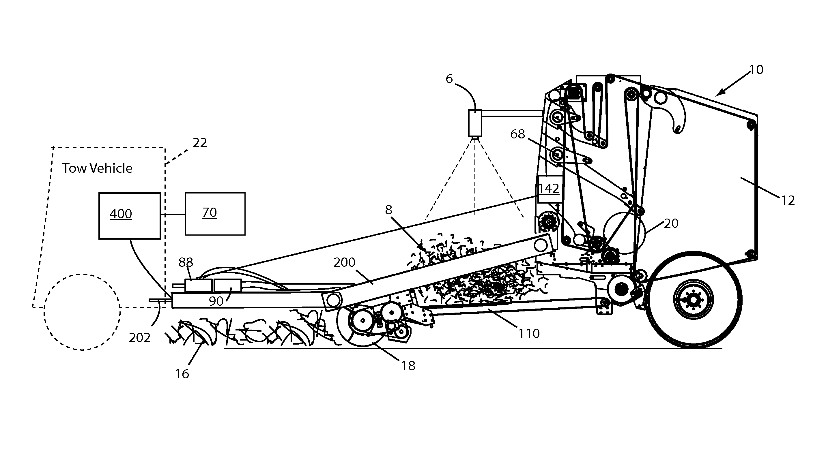
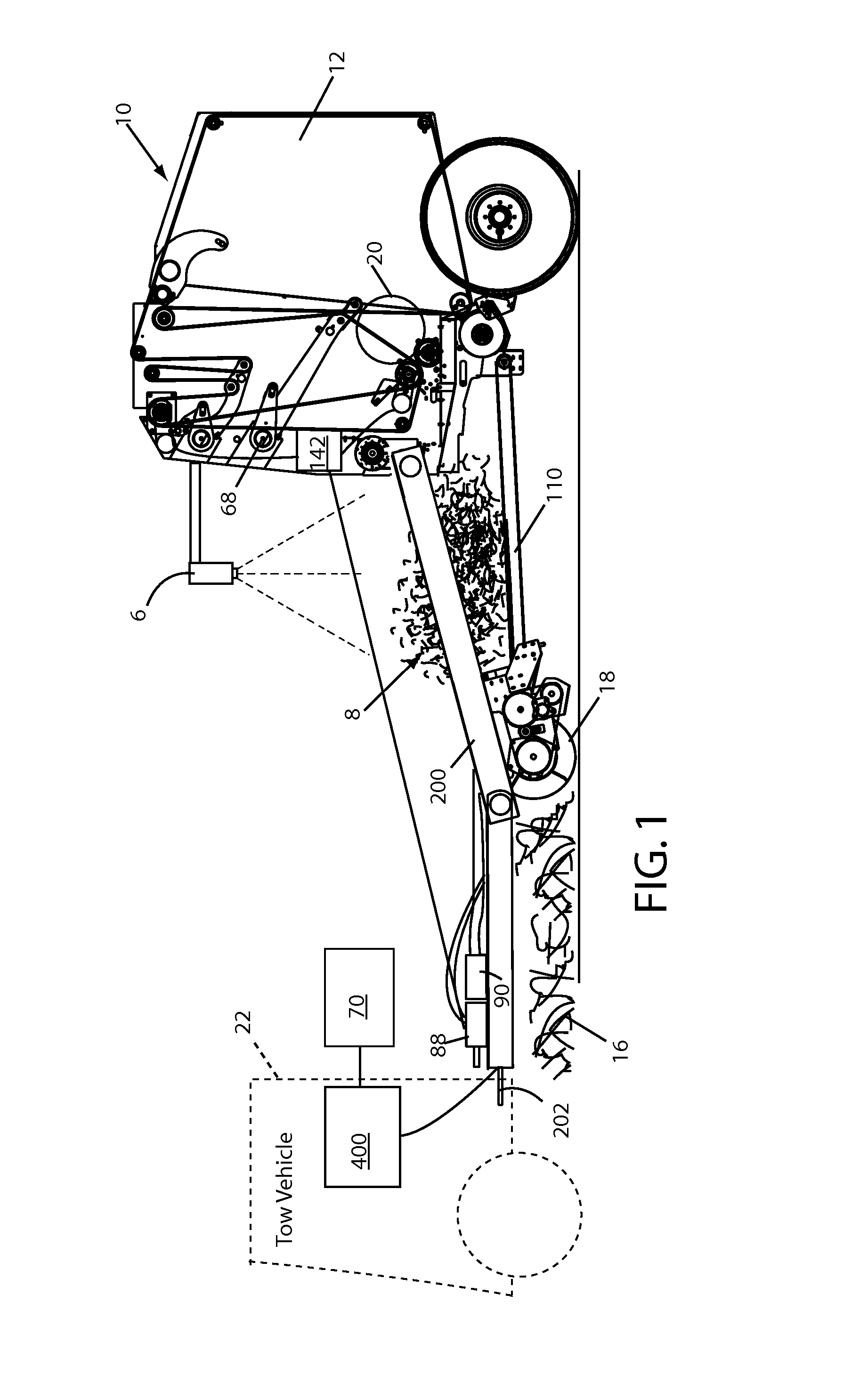
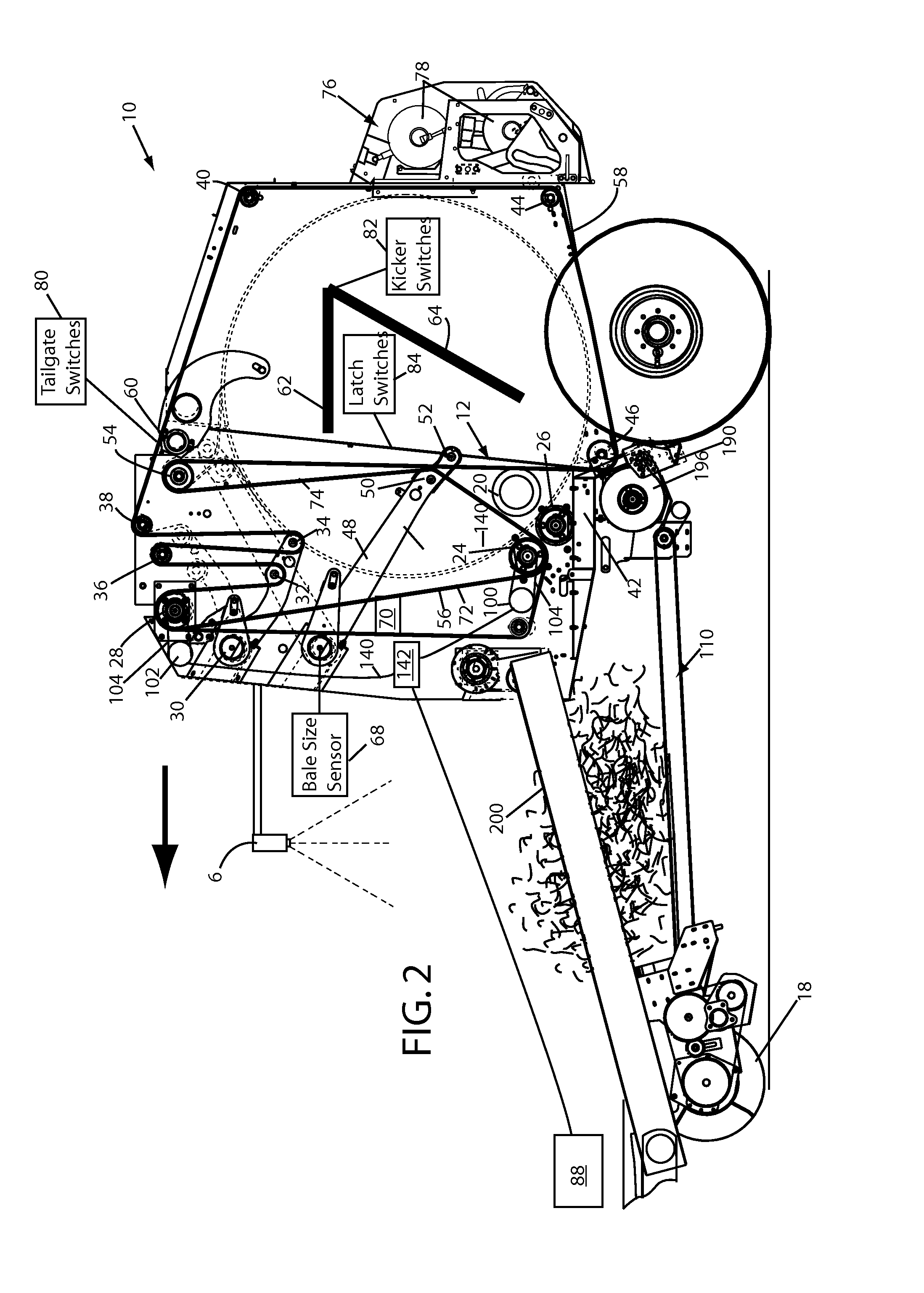
[0020]As required, example embodiments of the present invention are disclosed herein. The various embodiments are meant to be non-limiting examples of various ways of implementing the invention and it will be understood that the invention may be embodied in alternative forms. The present invention will be described more fully hereinafter with reference to the accompanying drawings in which like numerals represent like elements throughout the several figures, and in which example embodiments are shown. The figures are not necessarily to scale and some features may be exaggerated or minimized to show details of particular elements, while related elements may have been eliminated to prevent obscuring novel aspects. The specific structural and functional details disclosed herein should not be interpreted as limiting, but merely as a basis for the claims and as a representative basis for teaching one skilled in the art to variously employ the present invention.

[0021]It should be noted th...


PUM


Abstract

In an example embodiment, a sensor detects a characteristic of accumulated crop material and a controller manipulates the speed of a baling chamber in response thereto. In an example method, the speed of a baling chamber of a variable speed baler is manipulated in response to a characteristic of an accumulated crop material. For example, the height of accumulated crop material in an accumulation area may be detected and the speed of the baling chamber manipulated in response thereto. The rate of growth of the bale may also be determined and used in manipulating the speed of the baling chamber.

Description

[0001]BACKGROUND OF INVENTION[0002]1. Field of Invention[0003]The present invention relates generally to round balers, and more specifically, to round balers with rotational baling chambers.[0004]2. Description of Related Art[0005]Conventional round balers receive crop material and form the crop material into compacted bales in a baling chamber. There are generally three major cycles in the operation of a round baler: a bale-forming cycle, a bale-wrapping cycle, and a bale-ejecting cycle. The baling chamber is typically run at a constant rotational speed throughout its bale-forming and bale-wrapping cycles.[0006]An important part of operating a round baler is controlling the feed rate of material into the bale chamber. If too much material is fed to the bale chamber it can plug the baler, whereas if too little material is fed then the bale will deteriorate in the chamber. In a conventional round baler pulled with a tractor, controlling the feed rate is accomplished by varying the tr...

Claims


Application Information

Patent Timeline
IPC IPC(8): A01F15/08A01F15/07
CPCA01F15/08A01F15/07A01F15/085A01F15/0833A01F2015/076
Inventor OLANDER, BRIANHERRON, MAYNARD
Owner AGCO CORP
Why Eureka
Try Eureka