Liquid ejecting apparatus

a technology of liquid ejecting apparatus and ejector, which is applied in the direction of printing, other printing apparatus, etc., can solve the problems of not being able to control such a gloss degree according to the intended use, and achieve the effect of simplifying configuration and reducing the number of heaters

Active Publication Date: 2014-12-25
SEIKO EPSON CORP
View PDF3 Cites 9 Cited by
  • Summary
  • Abstract
  • Description
  • Claims
  • Application Information

AI Technical Summary

Benefits of technology

[0023]According to this configuration, the number of heate

Problems solved by technology

It has not been easy to control such a gl

Method used


Image

  • Liquid ejecting apparatus
  • Liquid ejecting apparatus
  • Liquid ejecting apparatus

Examples


Embodiment Construction

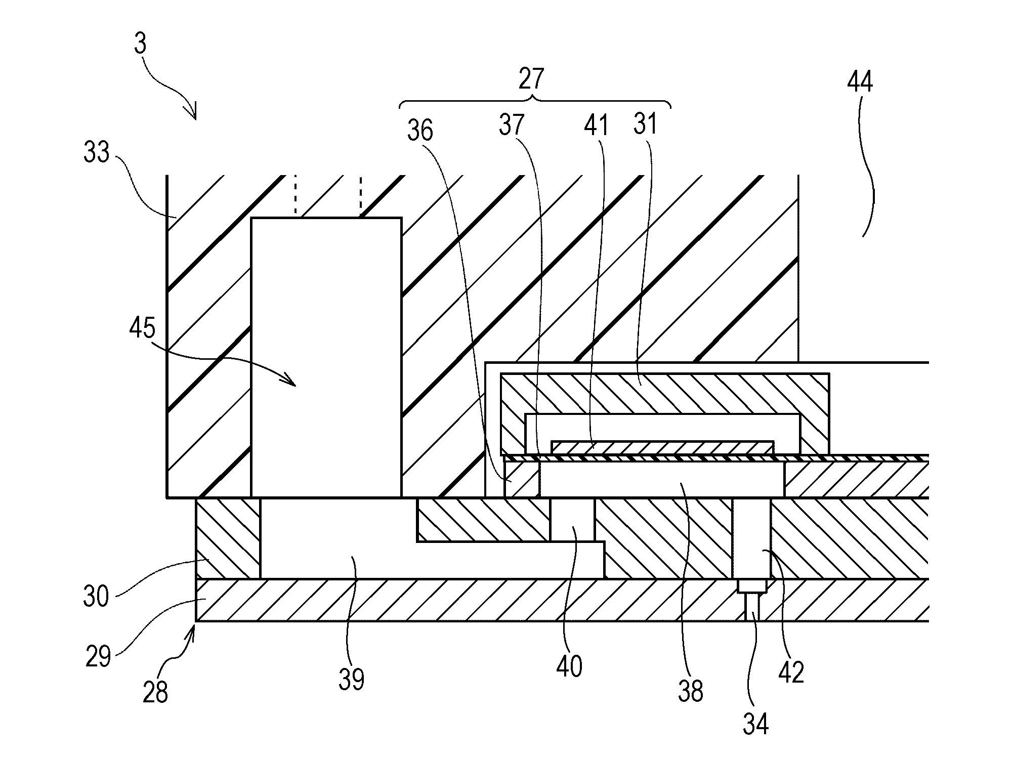
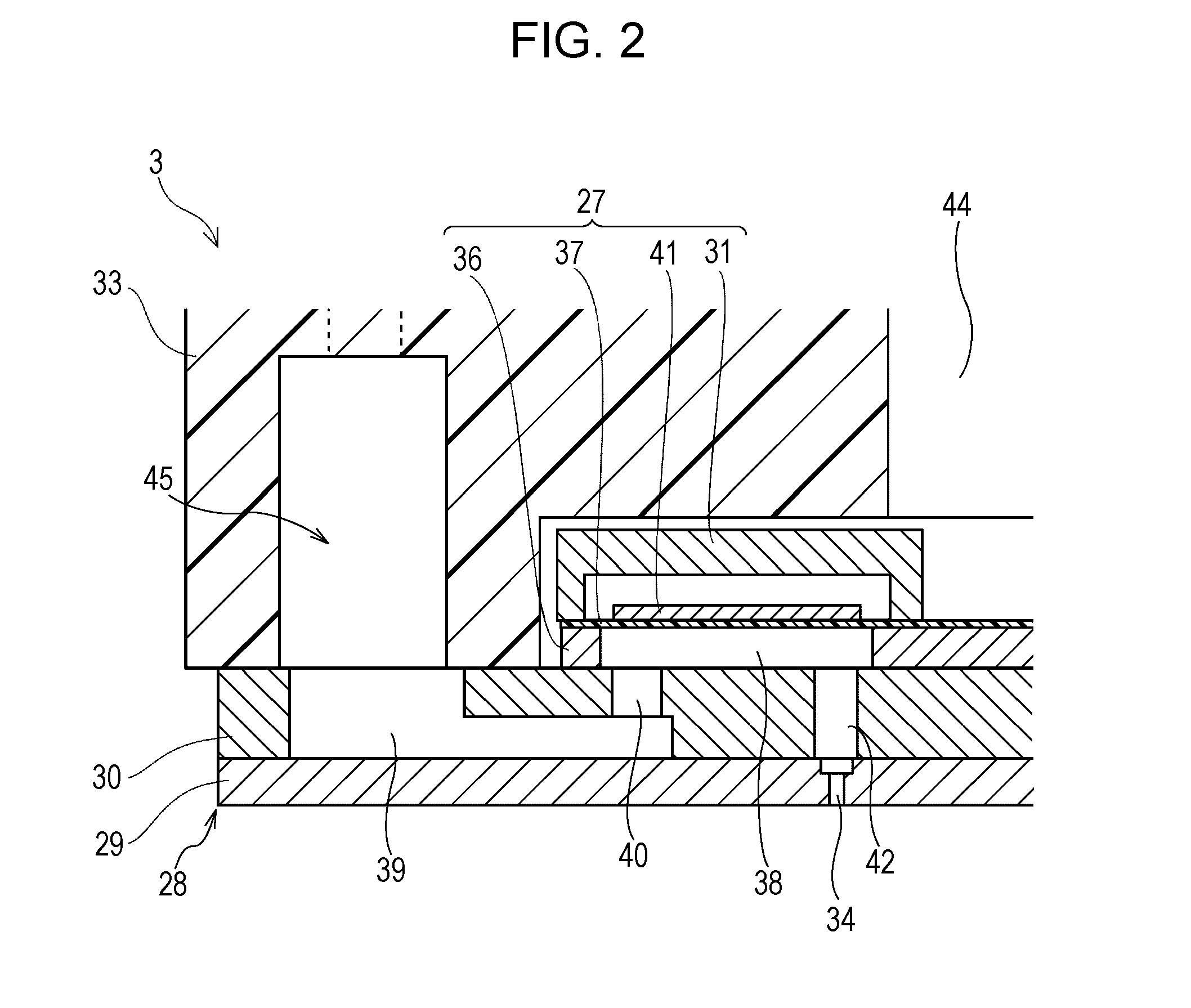
[0030]Hereinafter, aspects for carrying out the invention are described with reference to the accompanying drawings. Embodiments described below are variously limited as a suitable example of the invention but the scope of the invention is not limited to the aspects insofar as there is particularly no description for limiting the invention in the following description. In the following description, an ink jet printer 1 (hereinafter referred to as a printer) in an ink jet recording head (hereinafter referred to as a recording head) which is one kind of a liquid ejecting head is mentioned as an example of the liquid ejecting apparatus of the invention.

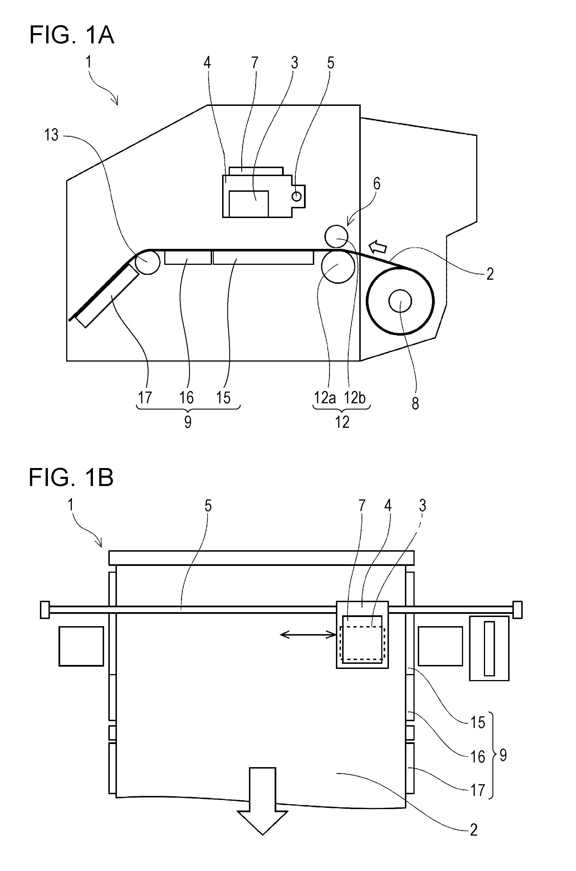
[0031]The configuration of the printer 1 is described with reference to FIGS. 1A and 1B. The printer 1 is a device of ejecting a liquid ink onto the surface of a recording medium 2 (one kind a landing target, which is also referred to as a target recording medium), and then recording an image and the like. The printer 1 has a recording h...


PUM


Abstract

A liquid ejecting apparatus has a liquid ejecting head capable of ejecting an ink containing thermoplastic resin particles from nozzles to a landing target and a heating unit of heating ink droplets landing on the landing target, in which the heating unit heats the ink droplets at a filming control temperature according to the minimum film forming temperature at which the filming of the surface of the ink droplets starts to thereby control the filming degree of the surface of the ink droplets.

Description

BACKGROUND[0001]1. Technical Field[0002]The present invention relates to a liquid ejecting apparatus having a liquid ejecting head which ejects an ink containing thermoplastic resin particles from nozzles.[0003]2. Related Art[0004]The liquid ejecting apparatus has a liquid ejecting head and ejects various kinds of liquid from this ejecting head. As the liquid ejecting apparatus, image recorders, such as an ink jet printer and an ink jet plotter which eject ink, are known, for example. In recent years, these image recorders have been demanded to record images and the like not only on ink-absorbing recording media (landing target) which are easy to absorb ink, such as paper and cloth, but on non-ink-absorbing recording media which do not absorb ink, such as a plastic film.[0005]In order to fix ink on the non-ink-absorbing recording media described above, one which ejects an ink containing thermoplastic resin particles, and then drying the ink landing on the recording media by a heatin...

Claims


Application Information

Patent Timeline
IPC IPC(8): B41J11/00
CPCB41J11/002B41J11/00242B41J11/00244
Inventor SATO, HIRONORIFUKUDA, MASAKOSAYAMA, TOMOHIRO
Owner SEIKO EPSON CORP
Why Eureka
Try Eureka