
Lane monitoring with electronic horizon

a technology of electronic horizon and lane monitoring, applied in the direction of process and machine control, instruments, navigation instruments, etc., can solve the problems of optical system not being able to detect the lane location, wear and tear of the lane surface, and the difficulty of detecting the lane location, etc., to achieve enhanced validation of the geopositioning data

Active Publication Date: 2014-12-25
FORD GLOBAL TECH LLC
View PDF26 Cites 46 Cited by
  • Summary
  • Abstract
  • Description
  • Claims
  • Application Information

AI Technical Summary

Benefits of technology

The patent uses an optical system as the main detector and a geopositioning system as a backup in case of an optical data failure. The geopositioning data is validated during times when optical data is available by adjusting offsets. The technical effect is an improved accuracy and reliability in detecting and tracking objects using a combination of optical and geopositioning systems.

Problems solved by technology

However, the lane markings on road surfaces can still be hard to detect.
They may be worn away or covered by dirt.
There are many other possible impediments that cause the optical system to fail to detect the lane location, such as shadows, overhead bridges, rain, and snow.
In such cases, gaps may form in the representation of the lane being tracked.
Nevertheless, instances still occur when the camera-based system is unable to produce a valid output.
Even in the event that a digital map database does directly represent actual lane boundaries for a given roadway, issues of sporadic positional errors and intermittent availability of the geopositioning systems have limited the reliability of these systems.

Method used


Image

  • Lane monitoring with electronic horizon
  • Lane monitoring with electronic horizon
  • Lane monitoring with electronic horizon

Examples


Embodiment Construction

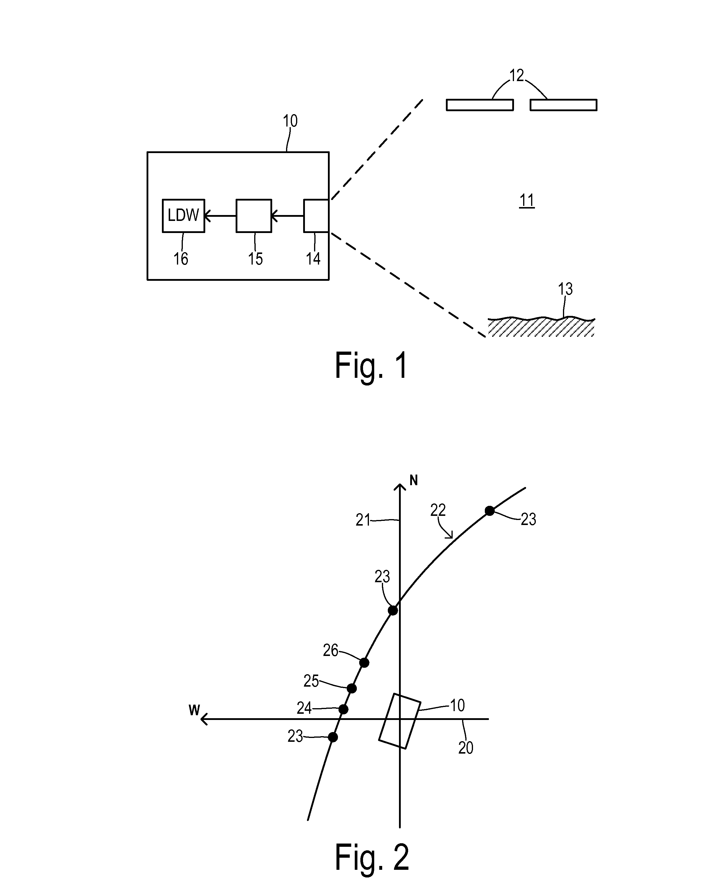
[0019]Referring now to FIG. 1, a vehicle 10 moves along a roadway 11 in a lane bordered by painted lane lines 12 and a road edge 13. Vehicle 10 includes a camera system 14 coupled to a lane monitoring module 15 which may include a pattern recognizer for detecting lane markings such as lane lines 12 and road edge 13 in order to monitor the position of vehicle 10 relative to a detected lane. Information concerning the relative position of vehicle 10 and the edges of detected lanes around vehicle 10 is provided to a lane departure warning system 16 which may generate a driver alert in the event that vehicle 10 starts to wander out of its lane. Another type of driver assistance system that depends on the lane position information is an adaptive cruise control system, wherein target vehicle selection is improved by the use of EH and camera-based lane information. In general, the driver assistance system controls a driver assistance parameter (e.g., the generation of a warning or adjustin...


PUM


Abstract

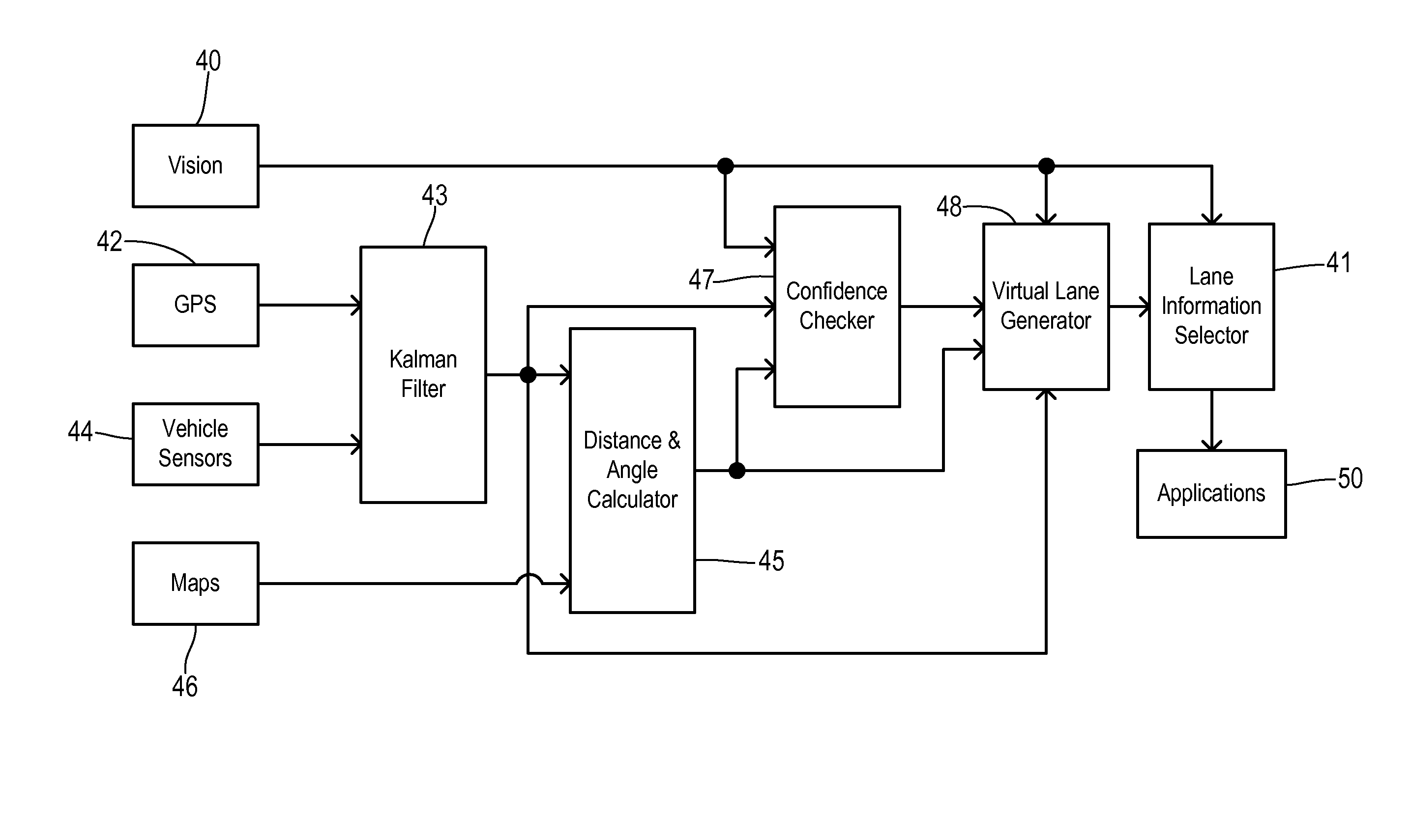
Apparatus for a vehicle operated on a roadway having lane markers includes an optical sensor providing optical data of the roadway. A first lane model is stored in an electronic memory in response to detected lane markers in the optical data. An electronic horizon system tracks a position of the vehicle and provides roadway data in response to the position. A second lane model is stored in the electronic memory in response to the roadway data. A confidence checker compares a discrepancy between the first and second lane models to a threshold in order to determine a confidence level. An output selector selects the first lane model when lane markers are detected in the optical data, and selects the second lane model if the lane markers are not detected in the optical data and the confidence level is greater than a predetermined level.

Description

CROSS REFERENCE TO RELATED APPLICATIONS[0001]Not Applicable.STATEMENT REGARDING FEDERALLY SPONSORED RESEARCH[0002]Not Applicable.BACKGROUND OF THE INVENTION[0003]The present invention relates in general to monitoring a location of a roadway lane relative to a vehicle, and, more specifically, to improved lane detection during times when optical identifiers are not present.[0004]Automatic lane detection and monitoring is useful for supporting various driver assistance systems such as a lane departure warning system or a lane keeping assist system. The primary sensor being used in conventional lane detection systems is vision-based, e.g., an optical camera. A lane detection algorithm detects lane markings such as painted lane lines or surface features corresponding to a road edge, and then estimates a vehicle's lateral position within the lane, the lane width, and the vehicle's heading angle with respect to the lane.[0005]Currently used image processing technologies in lane detection a...

Claims


Application Information

Patent Timeline
Patent Type & Authority Applications(United States)
IPC IPC(8): G01C21/30
CPCG01C21/30B60W30/12B60W2050/0091B60W2050/0215B60W2556/50G06V20/588B60W2420/403
Inventor JOH, PETER G.PILUTTI, THOMAS E.RUPP, MATT Y.SPERO, DORIAN JACKWOLSKI, BRIAN
Owner FORD GLOBAL TECH LLC
Learn More