Cpap pillow apparatus and method

a pillow and pillow body technology, applied in the field of pillow body apparatus, can solve the problems of increased contact between the pillow area and the patient's body, increased contact between the pillow and the patient, and loss of pressurized air from the breathing circui

Active Publication Date: 2015-01-01
RANDALL BRET
View PDF1 Cites 42 Cited by
  • Summary
  • Abstract
  • Description
  • Claims
  • Application Information

AI Technical Summary

Benefits of technology

[0035]During setup, the user causes a consolidating of the fill, in unobstructed fall toward the first wall, by suspending the shell, containing the fill, from the joinder. After placing the pillow on a sleeping surface with the bottom closest thereto, a user takes his or her place with head, neck, and possibly shoulders on the top, above the fill. This should be done with a dynamic movement to apply a threshold level of force by a portion of the user against the top. The re

Problems solved by technology

Obstruction of the airway during sleep results in snoring and sleep apnea.
Whenever that seal is broken, such as through movement during sleep and contact with the patient's pillow, pressurized air from the breathing circuit is lost.
Conventional sleeping pillows made with resilient and pre-loaded materials present problems because the weight of the patient's head causes the pillow in the area of the head to be depressed, leaving the surrounding surface of the pillow to push, unweighted, to a level relatively higher than the head.
This results in increased contact between the pillow areas around the patient's therapeutic mask, particularly in side and stomach sleeping positions.
Thus, the pillow will tend to fluff-up and fill-out the pillow case or the cover around the pillow filling material.
However, a pillow is actually “pre-loaded” such that a certain amount of force is required before the pillow begins to make any appreciable displacement or deflection.
A fully resilient pi

Method used


Image

  • Cpap pillow apparatus and method
  • Cpap pillow apparatus and method
  • Cpap pillow apparatus and method

Examples


Embodiment Construction

[0083]It will be readily understood that the components of the present invention, as generally described and illustrated in the drawings herein, could be arranged and designed in a wide variety of different configurations. Thus, the following more detailed description of the embodiments of the system and method of the present invention, as represented in the drawings, is not intended to limit the scope of the invention, as claimed, but is merely representative of various embodiments of the invention. The illustrated embodiments of the invention will be best understood by reference to the drawings, wherein like parts are designated by like numerals throughout.

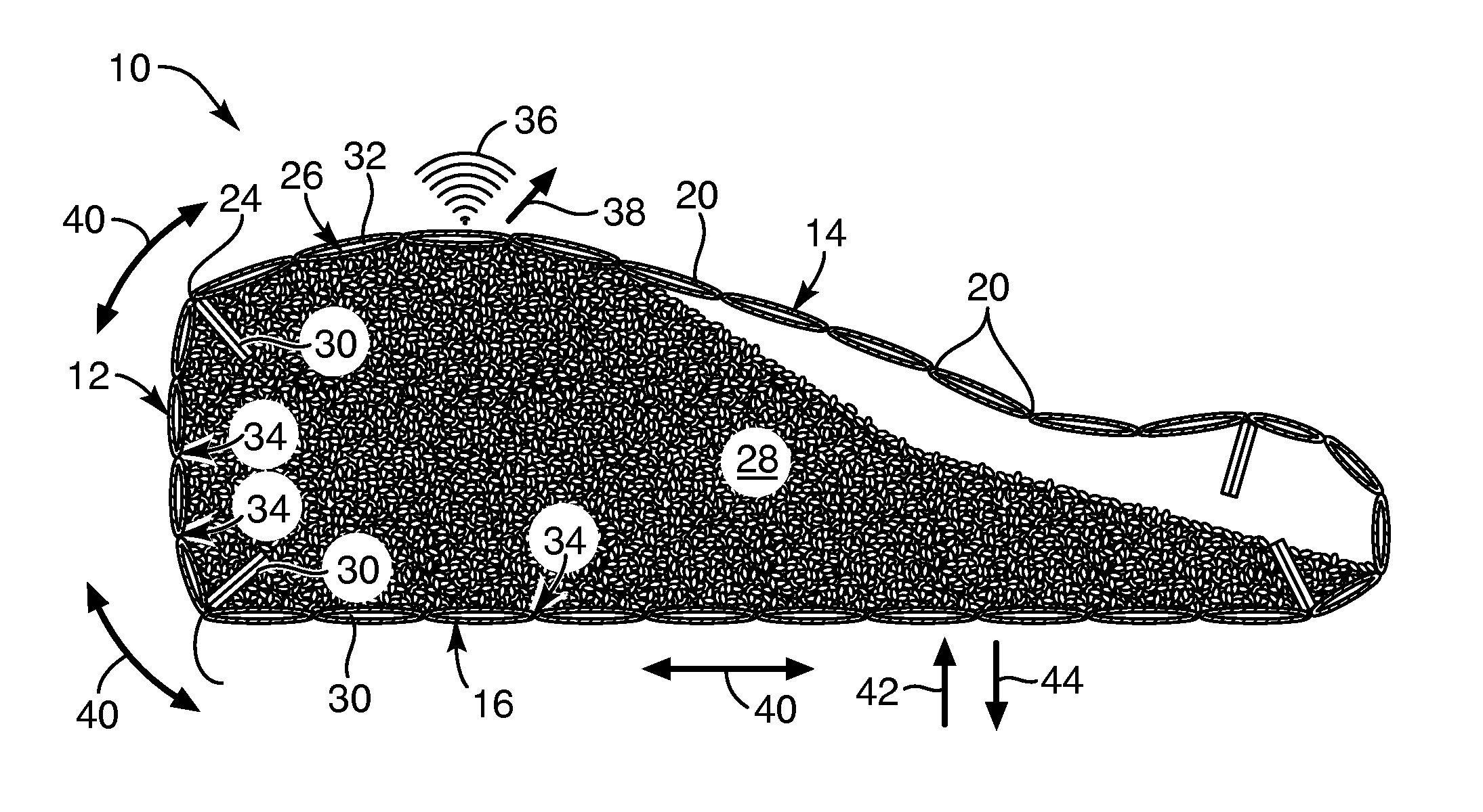
[0084]A fundamental problem with pillows is found in the exact reason they exist. A pillow is a supporting member. A pillow may be used behind the back supporting the user in a sitting position, such as reading in bed Likewise, a pillow may be used to elevate the head, neck, shoulders, feet, or the like. Thus, pillows represent ...


PUM

PropertyMeasurementUnit
Forceaaaaaaaaaa
Pressureaaaaaaaaaa
Volumeaaaaaaaaaa

Abstract

A pillow relies on a shell containing two types of fill material, one comparatively smaller, granular, and characterized by a comparatively larger spring constant, and another comparatively larger, more chunky in shape, and characterized by a comparatively smaller spring constant. Below a threshold level of force (or pressure, which is force per unit area) the larger, softer, second fill material resists flow of the smaller, harder, stiffer fill material. However, upon application of a force (or pressure) above some threshold, the mixture of the two fill materials will flow to conform the pillow to the shape of a user. The pillow will then substantially stabilize in that shape in the absence of forces above the threshold level.

Description

RELATED APPLICATIONS[0001]This application: claims the benefit of co-pending U.S. Provisional Patent Application Ser. No. 62 / 027,729, filed Jul. 22, 2014; and is a continuation in part of U.S. patent application Ser. No. 12 / 701,544, filed Feb. 6, 2010, which claims the benefit of U.S. Provisional Patent Application Ser. No. 61 / 303,564, filed Feb. 10, 2010; all of which are hereby incorporated by reference in their entirety.BACKGROUND[0002]1. The Field of the Invention[0003]This invention relates to sleeping apparatus and, more particularly, to novel systems and methods for making and using specialty pillows and adjustable pillow for supporting the body during sleep.[0004]2. The Background Art[0005]Pillows are used during sleep both for comfort and for positioning the head or other bodily member in desired orientations. In the womb and for a period of time after birth, a baby's spine is shaped like a letter C. As the baby develops, secondary curves known as Lordotic develop in the ce...

Claims


Application Information

Patent Timeline
IPC IPC(8): A61F5/56B68G15/00A47G9/10
CPCA47G9/10B68G15/00A61F5/56Y10T29/481
Inventor RANDALL, BRET
Owner RANDALL BRET
Why Eureka
Try Eureka