
Method for the production of caps with a heat shrinkable skirt and caps obtained according to the method

a production method and technology of a heat shrinkable skirt, applied in the field of closed caps, can solve the problems of low efficiency of the method, insufficient flexibility of the known method, and use of an irradiation device with an investment cost and an operating cos

Active Publication Date: 2007-06-14
ALCAN PACKAGING CAPSULES
View PDF8 Cites 1 Cited by
  • Summary
  • Abstract
  • Description
  • Claims
  • Application Information

AI Technical Summary

Benefits of technology

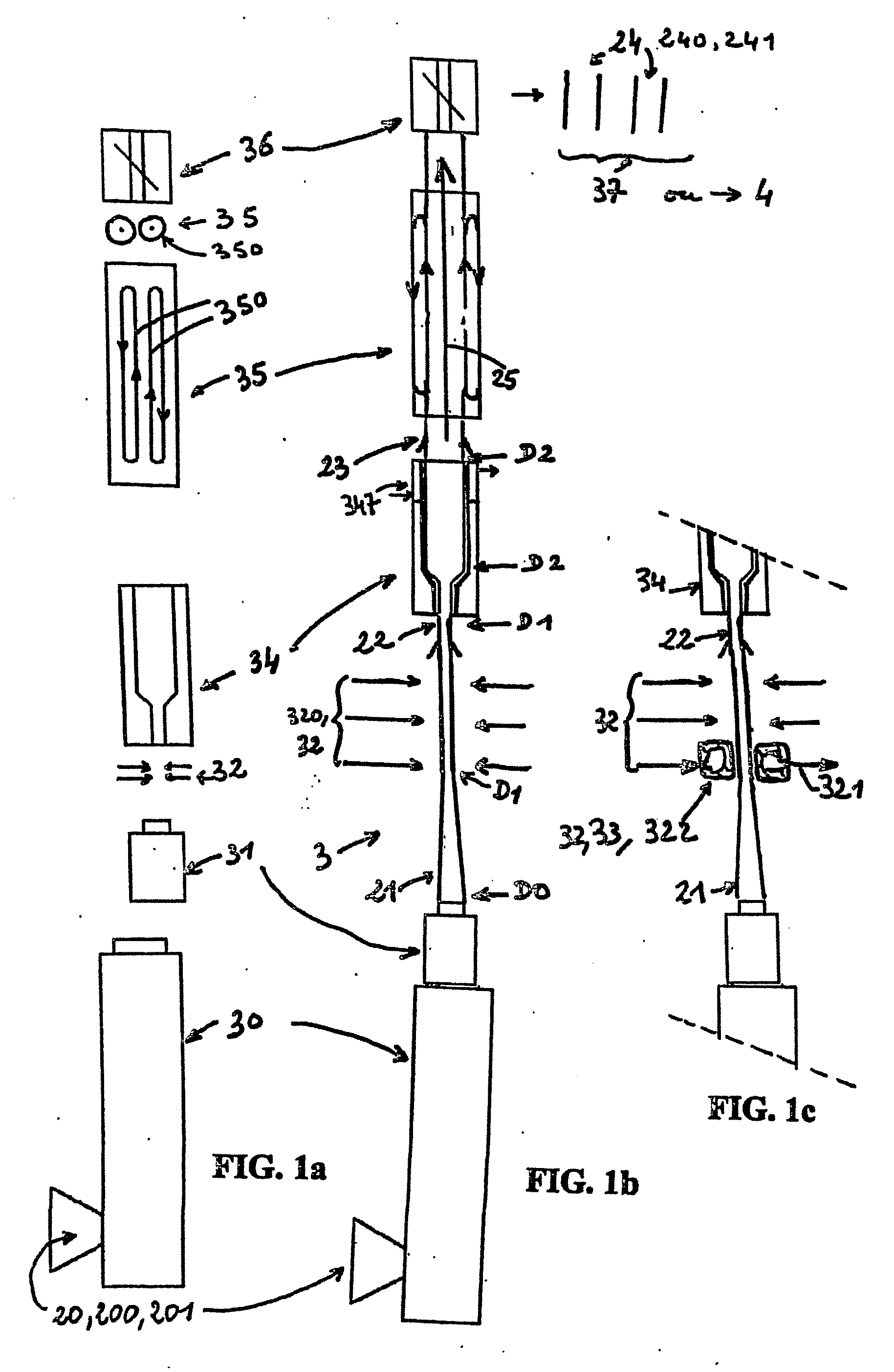
[0026] and is characterized in that a drawing step is included in which the extruded tube is drawn in the axial direction, at the exit from the die of the extruder between the extrusion step a) and the expansion step b), so as to obtain an axially drawn tube with diameter D1 typically less than diameter D0 and diameter D2, with thickness E1 typically less than thickness E0 and with a corresponding section with area SI, such that S0 / S1 typically ranges between 2 and 10, the extrusion, axial drawing, radial expansion and chopping steps being carried out continuously while moving so as to obtain caps that are both economic, easily heat shrinkable and with a stable axial dimension thereby avoiding any axial distortion, and particularly any axial distortion of the printout.
[0031] This method gives a means of solving the problems that arise. Firstly, it does not use any irradiation device, such that the disadvantage in the previous method developed by the applicant is eliminated, related particularly to the negative image of any type of irradiation with the general public.
[0033] Finally, the method according to the invention was tested with a large number of different materials and combinations of different thermoplastic materials, both in the form of a single layer extruded material and in the form of dual or three layer co-extruded material, such that it was possible to obtain a wide variety of caps with a different feel, appearance, elasticity, contact sonority with a more or less dull or crystalline sound, flexibility and cuttability with a knife, etc.

Problems solved by technology

Known caps or caps with heat shrinkable skirts, and particularly those described in French patent FR 2 817 193, have several disadvantages: firstly, they make use of an irradiation device that has an investment cost and an operating cost.
Furthermore, even if technically the caps thus manufactured do not introduce any risk for the user, some users will be reticent due to the association of “irradiation” and drink packaging means, even if this is unjustified, secondly, it has been observed that there are dimensional stability problems in the axial direction with caps once they have been heat shrunk onto necks, and since these caps are typically printed, these deformations modify the printing, furthermore, the hourly productivity of the method has been found to be too low, finally, the known method does not have sufficient flexibility to satisfy the diversity of new needs, both concerning sensorial properties of caps such as textures, feel or sonority during use or contact, in particular so as to obtain sensorial properties close to various caps considered as being top of the range on the market.

Method used


Image

  • Method for the production of caps with a heat shrinkable skirt and caps obtained according to the method
  • Method for the production of caps with a heat shrinkable skirt and caps obtained according to the method
  • Method for the production of caps with a heat shrinkable skirt and caps obtained according to the method

Examples


example embodiments

A) Manufacturing of Tube Portions

[0153] Most tests on manufacturing of tube portions were carried out with the device (3) shown in FIG. 1b. Other tests were carried out with the device shown in FIG. 1c.

[0154] In these tests, an extruder with a maximum flow of 50 kg / h of a thermoplastic material was used, for which the “length / diameter” ratio of the screw was equal to 30.

[0155] An annular die or extrusion head with a diameter D0 equal to 27 mm was used, the formed extruded tube having a thickness E0 of 0.7 mm and a temperature T typically varying from 190° to 240° C.

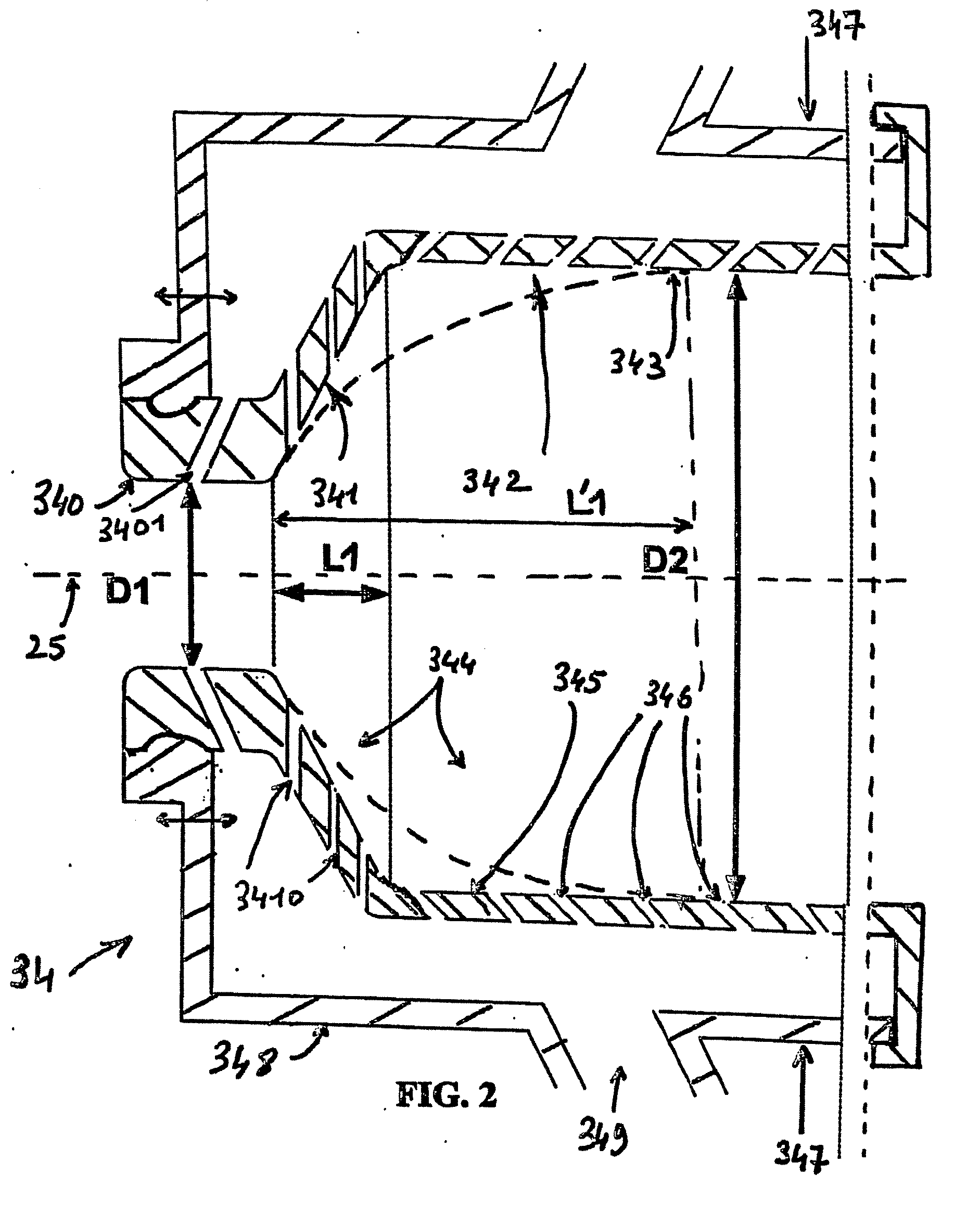
[0156] The radial expansion step was carried out over the axial distance L0 that typically varies from 0.3 m to 0.6 m, at the exit from the annular die. The axial drawing step was then blocked using blown air as the means of cooling the axially drawn tube, such that the axially drawn tube is at a temperature varying from 140° C. to 160° C. and its diameter is equal to the diameter D1 of the entry ring (340, 340′) to ...


PUM

PropertyMeasurementUnit
Temperatureaaaaaaaaaa

Abstract

The method comprises a) an extrusion stage wherein a extruded tube made of a thermoplastic material is formed by extrusion with the aid of an extrusion die having a diameter D0, a slit width E0 and a section S0; b) a stage wherein the extruded tube is radially expanded in order to form a radially expanded tube having a diameter D2, a thickness E2 and corresponding section of area S1; c) a truncating stage wherein the expanded tube is broken down into tube portions; d) a stage in which the tube portions are formed in such a way that a heat-shrinkable cap is obtained and in which an axial drawing stage is incorporated, between extrusion stage a) and expansion stage b), at the output of the extrusion die, in order to obtain an axially drawn tube having a diameter D1 which is typically smaller than D0 and D2, and a thickness E1 which is typically lower than E0, such that S0 / S1 typically ranges between 2 and 10. The advantages of the invention are as follows: it is possible to obtain caps which are economic, easily heat-shrinkable and which have a stable axial dimension, thereby avoiding any axial distortion, i.e. any axial distortion of the impression.

Description

FIELD OF THE INVENTION [0001] The invention relates to the field of closing caps for receptacles or bottles or outer closing for receptacles or bottles previously closed by a cork, a stopper or any other closing means. [0002] More particularly, the invention relates to the field of caps with a heat shrinkable skirt, in other words caps formed from a thermoplastic material that are shrunk onto the neck during crowning by the input of thermal energy, unlike metallic outer closing caps for which the skirt is crimped under the locking ring of the neck during crowning. [0003] More specifically, the invention relates to a new method for the production of caps with a heat shrinkable skirt, outer closing caps and possibly closing caps with a heat shrinkable skirt. BACKGROUND ART [0004] Heat shrinkable (HS for short) caps have been known for a long time. [0005] Thus, patent FR 805.771 describes the production of a PVC based cap formed by extrusion of a PVC based tube, and then after elongati...

Claims


Application Information

Patent Timeline
IPC IPC(8): B65D51/00B65D39/00B29C48/00B29C48/10B29C55/22B29C61/08B65D41/24B65D41/62
CPCB29C47/00B29C47/0026B29C55/22B29C61/08B29K2023/06B29K2023/083B29K2023/12B29K2027/06B29K2033/12B29K2067/00B29K2995/0049B29L2031/565B65D41/24B65D41/62B29C48/00B29C48/10
Inventor GRANGER, JACQUESLUCIANI, ANDRE
Owner ALCAN PACKAGING CAPSULES
Learn More