Method and apparatus for scanning an object

a technology of object scanning and scanning method, applied in the direction of instruments, specific gravity measurement, measurement devices, etc., can solve the problem that the available techniques are not well-suited for scanning complex shapes

Active Publication Date: 2015-01-01
SYST TECSCAN
View PDF27 Cites 21 Cited by
  • Summary
  • Abstract
  • Description
  • Claims
  • Application Information

AI Technical Summary

Benefits of technology

[0009]According to the present disclosure, there is also provided an apparatus for scanning an object. The apparatus comprises a movable support, a probe and a controller. The probe is mounted on the movable support. The controller is operably con...

Problems solved by technology

Currently available techniques are not well-suited for scanning of comple...

Method used


Image

  • Method and apparatus for scanning an object
  • Method and apparatus for scanning an object
  • Method and apparatus for scanning an object

Examples


Embodiment Construction

[0025]Like numerals represent like features on the various drawings.

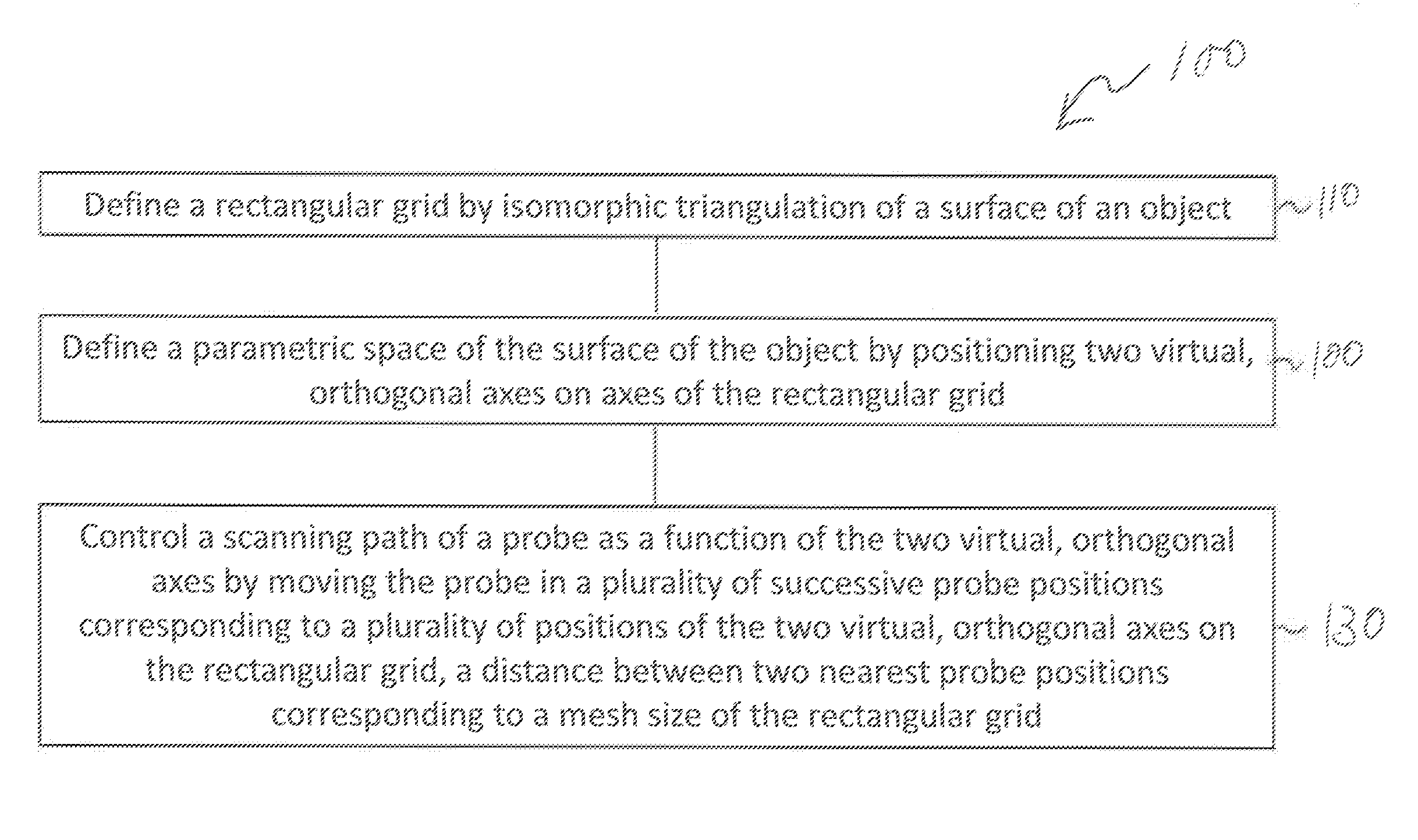
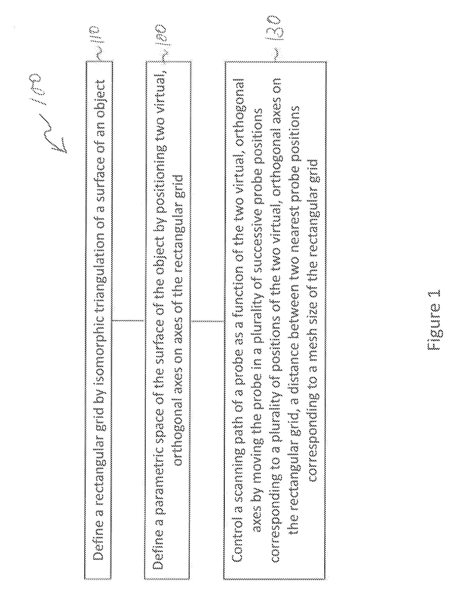
[0026]Various aspects of the present disclosure generally address one or more of the problems of scanning of complex shapes, including without limitations curved shapes and those shapes presenting surfaces defined in a three-dimensional (3D) space.

[0027]The following terminology is used throughout the present

DISCLOSURE

[0028]Probe: a physical device capable of sending and / or receiving a signal towards an object under test.[0029]Scanning path: a series of consecutive positions of a scanner probe.[0030]Pulse: a brief signal emitted by a probe.[0031]Isomorphic triangulation: mapping of a surface into a plurality of adjoining triangles using a constant arrangement of triangles of variable dimension and angles, in which the number of adjacent triangles attached to each vertex enclosed within the boundaries of the surface remains constant throughout the whole surface of an object.[0032]Rectangular grid: tessellation of a s...


PUM


Abstract

The present disclosure relates to a method and an apparatus for scanning an object. Two virtual, orthogonal axes are positioned on a surface of the object. A scanning path of a moving probe is controlled as a function of the two virtual, orthogonal axes. The scanning path can include a plurality of probe positions determined according to a desired coverage of the object. A single probe can be used or, optionally, a pair of probes or an array of probes can be used, optionally mounting the probes on a multi-axis movable support. Optionally, a computer-aided design representing the object can be used to parameterize the object. The method and apparatus can be used to create an image of the object for non-destructive testing.

Description

TECHNICAL FIELD[0001]The present disclosure relates to the field of non-destructive testing. More specifically, the present disclosure relates to a method and an apparatus for scanning an object.BACKGROUND[0002]Mechanical scanning of regularly shaped objects, such as for example flat or slightly curved objects, is well documented and widely used. A structure of an object is typically mapped by software using a grid, for example a rectangular grid, in which a length and a width of each rectangular pixel of the grid is identical. The grid is typically aligned with main axes of a scanner, designated axes x and y, and a scanning motion is obtained by moving a probe, for example an ultrasonic probe, along one axis or along a combination of axes (for instance x) and repeated after indexing along a perpendicular direction by moving one or a set of axes (for instance y), while maintaining a distance between the probe and the structure surface. Some systems use a plurality of such probes.[00...

Claims


Application Information

Patent Timeline
IPC IPC(8): G01N29/265
CPCG01N29/265G01N2291/2638G06F18/00
Inventor GRIMARD, NICOLASSICARD, RENESERHAN, SAM H.
Owner SYST TECSCAN
Why Eureka
Try Eureka