Storage stool

a storage stool and stool technology, applied in the field of storage stool, can solve the problems of poor load bearing capacity, unsafe use, unstably integrated stool stand, etc., and achieve the effects of not easy to deform, improve load bearing capacity, and be convenient to us

Inactive Publication Date: 2015-01-01
WANG CHUNSONG
View PDF7 Cites 5 Cited by
  • Summary
  • Abstract
  • Description
  • Claims
  • Application Information

AI Technical Summary

Benefits of technology

[0005]To overcome defects in the prior, the technical problem to be solved by the application is to provide a storage stool with a good bearing capacity and safe and convenient to use.
[0013]In comparison with the prior art, the application has the following advantages: the side wall uses the rigid material (hard paperboard) as the interlayer, so the bearing capacity is greatly improved, and use is safer; the bottom is supported by a rigid plate such that the whole structure is more stable and not easy to deform; the edge of the rigid plate is connected to the bottom of the inner face layer of the side wall, bringing convenience to dismantling; the stool lid engages with the storage chamber through the cover plate and therefore does not move relative to the stool stand and is more stably integrated, and the edge of the stool liquid is not required to be turned such that the production difficulty is greatly reduced and the production efficiency is improved; moreover, the bottom of the stool stand is provided with a rotary base allowing 360° rotation, so users can change direction without adjusting their posture. The storage stool is convenient.

Problems solved by technology

The existing storage stools usually have the following defects: 1. The load bearing capability is poor, and the use is unsafe; 2. The stool lid and the stool stand are unstably integrated and easy to move relatively; 3. The manufacturing is difficult, for example, folding the edge of the stool lid to form a lid edge.

Method used


Image

  • Storage stool
  • Storage stool
  • Storage stool

Examples


Embodiment Construction

[0027]The technical contents, structural characteristics, objectives and effects of the application are described in detail accompanying the following embodiments and attached drawings.

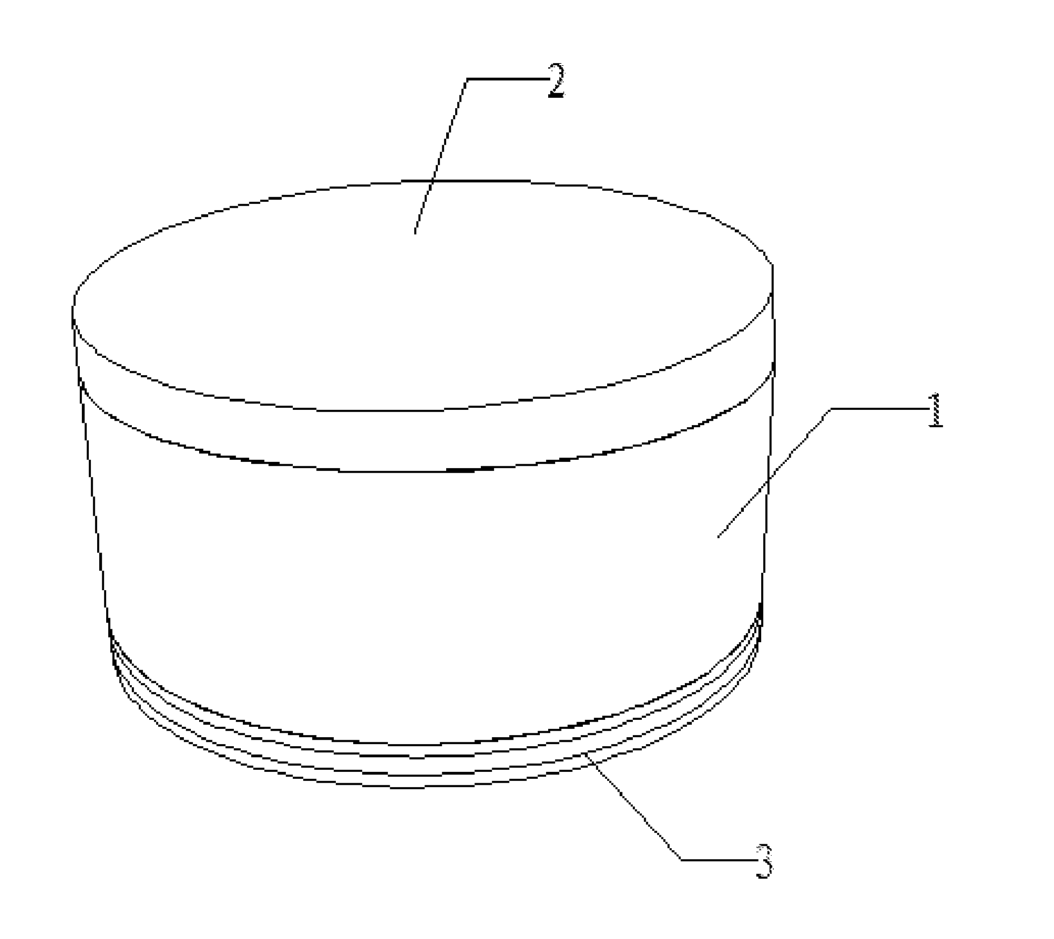
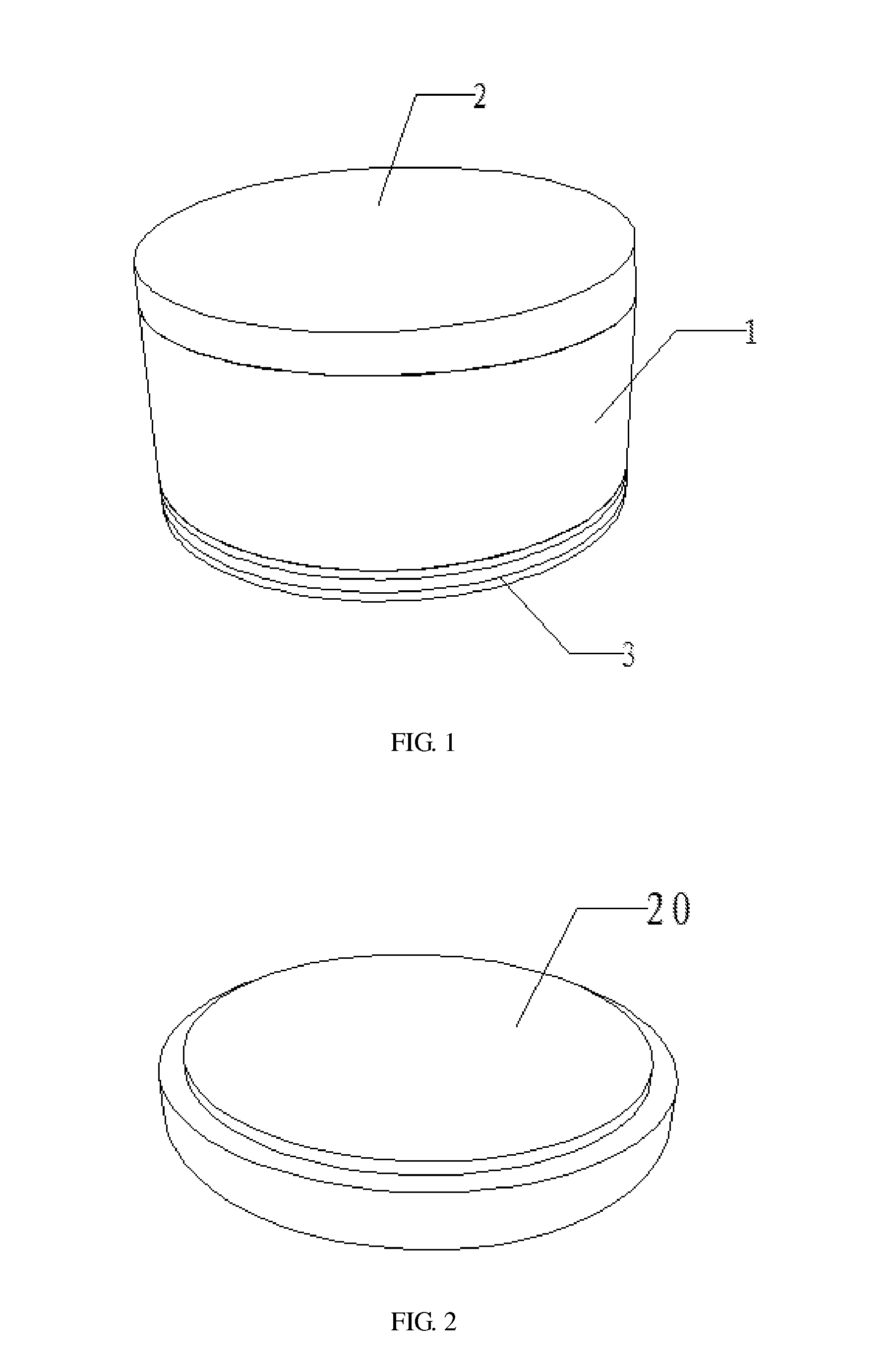
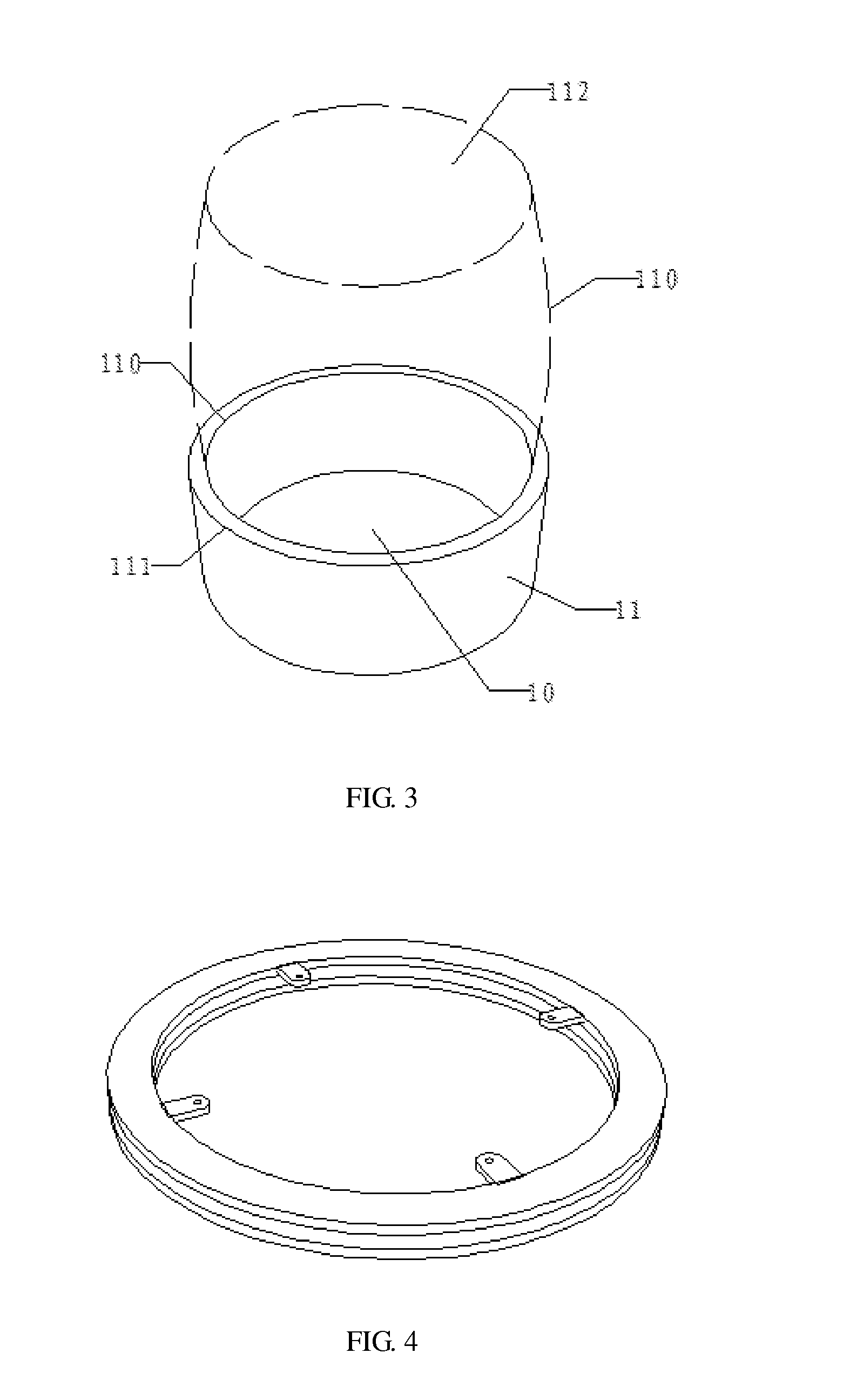
[0028]Refer to FIGS. 1 to 4. A storage stool is provided, comprising a stool stand 1 and a stool lid 2. The stool stand 1 comprises a bottom face 10 and a side wall 11 extending upward along the bottom face edge 10. The bottom face 10 and the side wall 11 together form a storage chamber with the upper end having an opening. The side wall 11 comprises an inner face layer 110, an outer surface layer 111 and an interlayer between the inner face layer 110 and the outer face layer 111. The interlayer has at least one layer made of a rigid material. The bottom of the stool stand 1 is detachably connected to a rotary base 3.

[0029]In the above embodiment, the stool stand 1 may be round, polygonal, square or rectangular, preferably round. The side wall 11 is sandwich structure, and the number of layers of the ...


PUM


Abstract

A storage stool provided includes a stool stand and a stool lid. The stool stand includes a bottom face and a side wall extending upward along the bottom face edge. The bottom face and the side wall together form a storage chamber with an upper end having an opening. The side wall includes an inner face layer, an outer surface layer and an interlayer clamped between the former two. The interlayer has at least one layer made of a rigid material. The bottom of the stool stand is detachably connected to a rotary base. With a paperboard as the interlayer of the side wall, the storage stool is greatly improved in bearing capacity and safer in use. With the rotary base at the bottom, the stool stand can rotate 360°, so users can change direction without adjusting their sitting posture. The use is very convenient.

Description

BACKGROUND OF THE INVENTION[0001]1. Technical Field[0002]The application relates to the field of storage suppliers, specifically to a storage stool.[0003]2. Description of Related Art[0004]Storage stools are a kind of novel household storage supplies and have around, polygonal, square and rectangular shapes. A typical storage stool comprises a stool stand and a stool lid. The stool stand is provided with a storage chamber with an opening upward. The stool lid is moveably covered on the stool stand. Items can be placed into or taken out from the storage chamber when the stool lid is removed. The storage stool can also be used as a stool when the stool lid is installed. The existing storage stools usually have the following defects: 1. The load bearing capability is poor, and the use is unsafe; 2. The stool lid and the stool stand are unstably integrated and easy to move relatively; 3. The manufacturing is difficult, for example, folding the edge of the stool lid to form a lid edge.BR...

Claims


Application Information

Patent Timeline
Patent Type & Authority Applications(United States)
IPC IPC(8): A47C9/00
CPCA47C9/00A47C3/00A47C3/18A47C7/62A47C3/16A47C7/628
Inventor WANG, CHUNSONG
Owner WANG CHUNSONG
Why Eureka
Try Eureka