
Mechatronic Circuit Breaker Device And Associated Tripping Method And Use Thereof In Interrupting A High Direct Current

a mechatronic circuit breaker and high direct current technology, applied in the direction of circuit-breaking switches, protective switch operating/release mechanisms, emergency protective arrangements for limiting excess voltage/current, etc., can solve the problem of not being able to use the thomson-type mechanical switch shown in fig. 5a, and not really clear whether and how it is possible to break direct current at very high peak-to-peak voltage levels. , the effect of dependency

Active Publication Date: 2015-01-01
ALSTOM TECH LTD
View PDF3 Cites 98 Cited by
  • Summary
  • Abstract
  • Description
  • Claims
  • Application Information

AI Technical Summary

Benefits of technology

The patent text describes a method for reducing leakage inductance in a circuit-breaker. Leakage inductance is the inductance that occurs when there is a connection between two parts of a circuit-breaker. This method involves measuring the self-inductance of each part of the circuit-breaker and adding a series inductance to limit the drift of current. The use of multiple power thyristors also contributes to the value of leakage inductance. The method also includes the step of eliminating any residual leakage currents by opening a disconnector. The technical effect of this patent is to reduce the leakage inductance in a circuit-breaker, which can improve the stability and reliability of the circuit.

Problems solved by technology

Although ideally adaptable to breaking high direct currents with IGCT thyristors as the breaker semiconductor components, it appears that the Thomson-type mechanical switch shown in FIG. 5A was not actually usable.
Moreover, on reading the above document, it is not really clear whether and how it is possible to break direct currents at very high peak-to-peak voltage levels, typically exceeding 50 kV.
This dependency is deleterious because the criteria for choosing the inherent frequency of this oscillatory circuit may lead to inherent frequencies that are too high given the technologies available for the production of the mechanical switch.
In other words, this principle is not applicable to direct current energy transmission applications when the nominal primary magnitudes respectively exceed a current of 1 kiloamp (kA) and a voltage of 100 kV.
Now, producing such an electromechanical circuit-breaker would require firstly very costly development work and secondly increased maintenance by virtue of the creation of an arc and thus of the associated wear.
Moreover, in all the embodiments proposed in the above application WO 2011 / 057675, no device is provided firstly for enabling protection of the IGBT transistors provided in the main branch, i.e. that carrying the steady current in the nominal regime, and secondly for facilitating switching the current to the auxiliary branch during switching from the ON state to the OFF state.
Finally, the major drawback of the proposed mechatronic circuit-breaker is that its operation assumes a very high driving power for effecting the instantaneous switching of all of the IGBT transistors of the main branch.
That time may be extremely long given the large dimensions necessary in the claimed applications to voltages exceeding 100 kV, for example.
Furthermore, controlling IGBT transistors in this way is in practice complex.

Method used


Image

  • Mechatronic Circuit Breaker Device And Associated Tripping Method And Use Thereof In Interrupting A High Direct Current
  • Mechatronic Circuit Breaker Device And Associated Tripping Method And Use Thereof In Interrupting A High Direct Current
  • Mechatronic Circuit Breaker Device And Associated Tripping Method And Use Thereof In Interrupting A High Direct Current

Examples


Embodiment Construction

[0061]Although specifically described with reference to the application of breaking high direct currents in a distribution and / or transmission line, other applications of the invention may be envisaged.

[0062]In particular, the mechatronic circuit-breaker of the invention may be used to break alternating currents.

[0063]The mechatronic circuit-breaker of the invention may also be used in a gas-insulated line (GIL).

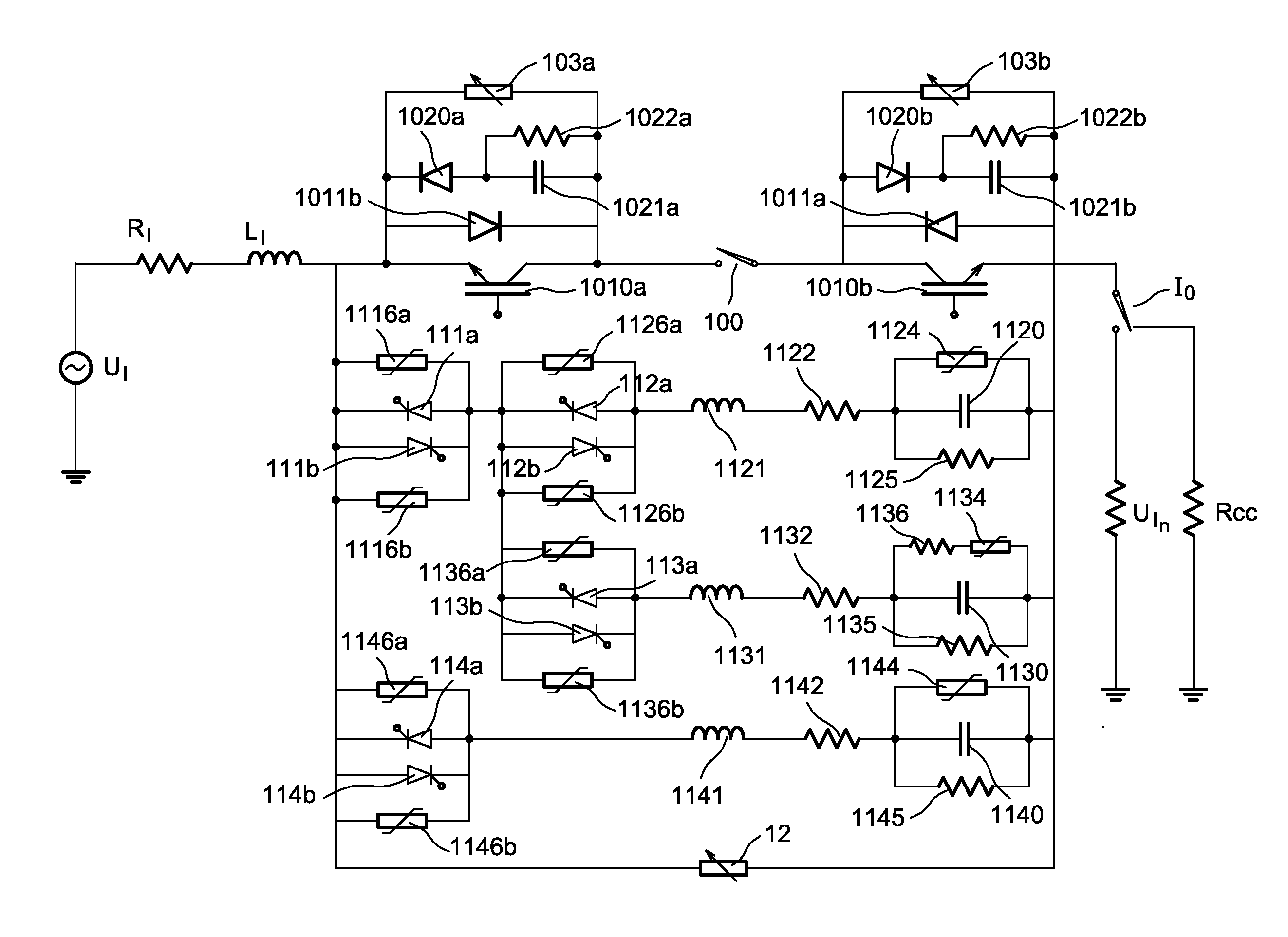
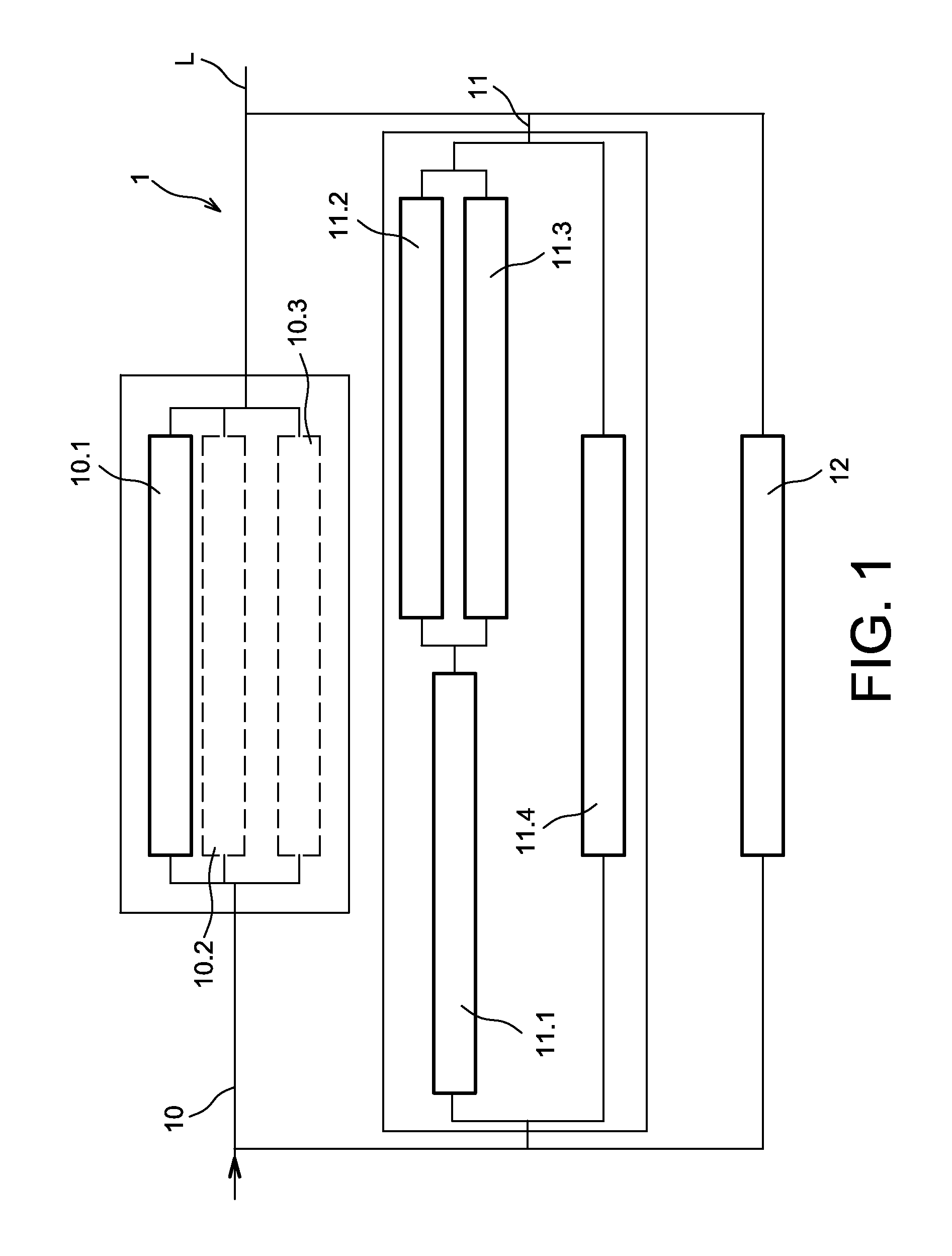
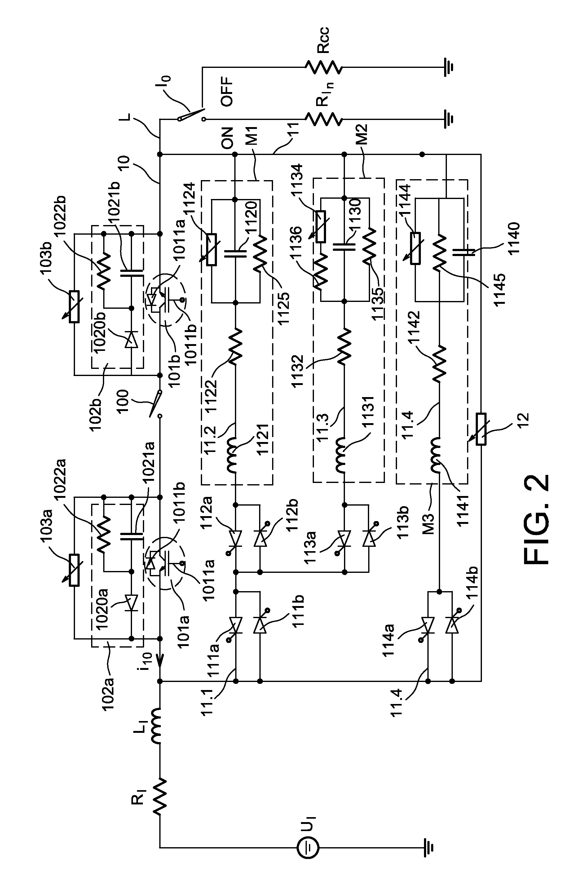
[0064]FIG. 1 shows an overall electrical architecture of a mechatronic circuit-breaker device 1 of the invention intended to break high direct currents in transmission networks L in a peak-to-peak voltage range up to 320 kV DC. The inventors moreover believe that in the future a mechatronic circuit-breaker of this kind could break direct currents in a peak-to-peak voltage range up to 500 kV or even beyond.

[0065]Such a device 1 comprises firstly a main branch 10 in which the primary current flows under steady conditions. It comprises a plurality of identical main modules 10.1...


PUM


Abstract

The invention relates to a new mechatronic circuit-breaker and its associated triggering method for breaking either alternating currents or direct currents at high voltages.

Description

TECHNICAL FIELD[0001]The invention relates to a new mechatronic circuit-breaker device and its associated triggering method.[0002]The main target application of the invention is to breaking high direct currents in a transmission and / or distribution line, typically at peak-to-peak voltage levels exceeding 50 kilovolts (kV) (DC), up to 800 kV (DC) and beyond. The expression high-voltage direct current (HVDC) is commonly used for this field of application.[0003]The invention may also be applied to breaking direct currents at lower peak-to-peak voltages, typically in the range 1 kV to 50 kV, or to breaking alternating currents.PRIOR ART[0004]Breaking currents in high-voltage direct current (HVDC) transmission and / or distribution networks has become of crucial importance because mastery thereof directly conditions the expansion of said networks.[0005]At present, a consensus seems to be emerging among all network players as to the approach to be adopted to effect such breaking: it is nece...

Claims


Application Information

Patent Timeline
Patent Type & Authority Applications(United States)
IPC IPC(8): H02H9/00H01H71/10
CPCH02H9/005H01H71/10H01H9/542H01H2009/544H01H9/548H01H2009/543H01H33/596
Inventor DUPRAZ, JEAN-PIERREGRIESHABER, WOLFGANGCOLLET, MICHEL
Owner ALSTOM TECH LTD
Learn More