
Method, optical system and lighting arrangement for homogenizing light

a technology of optical system and light ray, which is applied in the field of optical system and lighting arrangement for homogenizing bundles of light rays, can solve the problems of insufficient mixing of light rays in the far field of the mixing rod, insufficient exploration of inability to achieve the effect of fully exploring the precise relationship between mixing efficiency and light incidence points, reducing the number of stable trajectories, and improving light ray reflection. stability

Inactive Publication Date: 2015-01-01
KONINKLIJKE PHILIPS ELECTRONICS NV +1
View PDF9 Cites 9 Cited by
  • Summary
  • Abstract
  • Description
  • Claims
  • Application Information

AI Technical Summary

Benefits of technology

The present invention is a way to mix light rays by using an elongated optical element with curved edges and a rounded perimeter. This design helps to improve the mixing of light within the optical element compared to mixing rods without rounded corners. The rounded vertices in the optical element lead to a better mix of light rays compared to mixing rods with hexagonal cross-sections that only have flat edges. The invention also makes it easier to modify equipment for the manufacture of the optical element.

Problems solved by technology

Although hexagonal mixing rods are widely used nowadays, this geometrical shape does not provide an adequate homogeneity of the illuminance at the exit face of the mixing rod.
More specifically, the light rays are not adequately mixed in the far field of the mixing rod since the mixing does not sufficiently alter the angles of the light rays.
More specifically, the directing of the light into the mixing rod is dependent on the geometrical shape of the mixing rod, although the precise relationship between mixing efficiency and light incidence points have not been fully explored and reduced to practice.

Method used


Image

  • Method, optical system and lighting arrangement for homogenizing light
  • Method, optical system and lighting arrangement for homogenizing light
  • Method, optical system and lighting arrangement for homogenizing light

Examples


Embodiment Construction

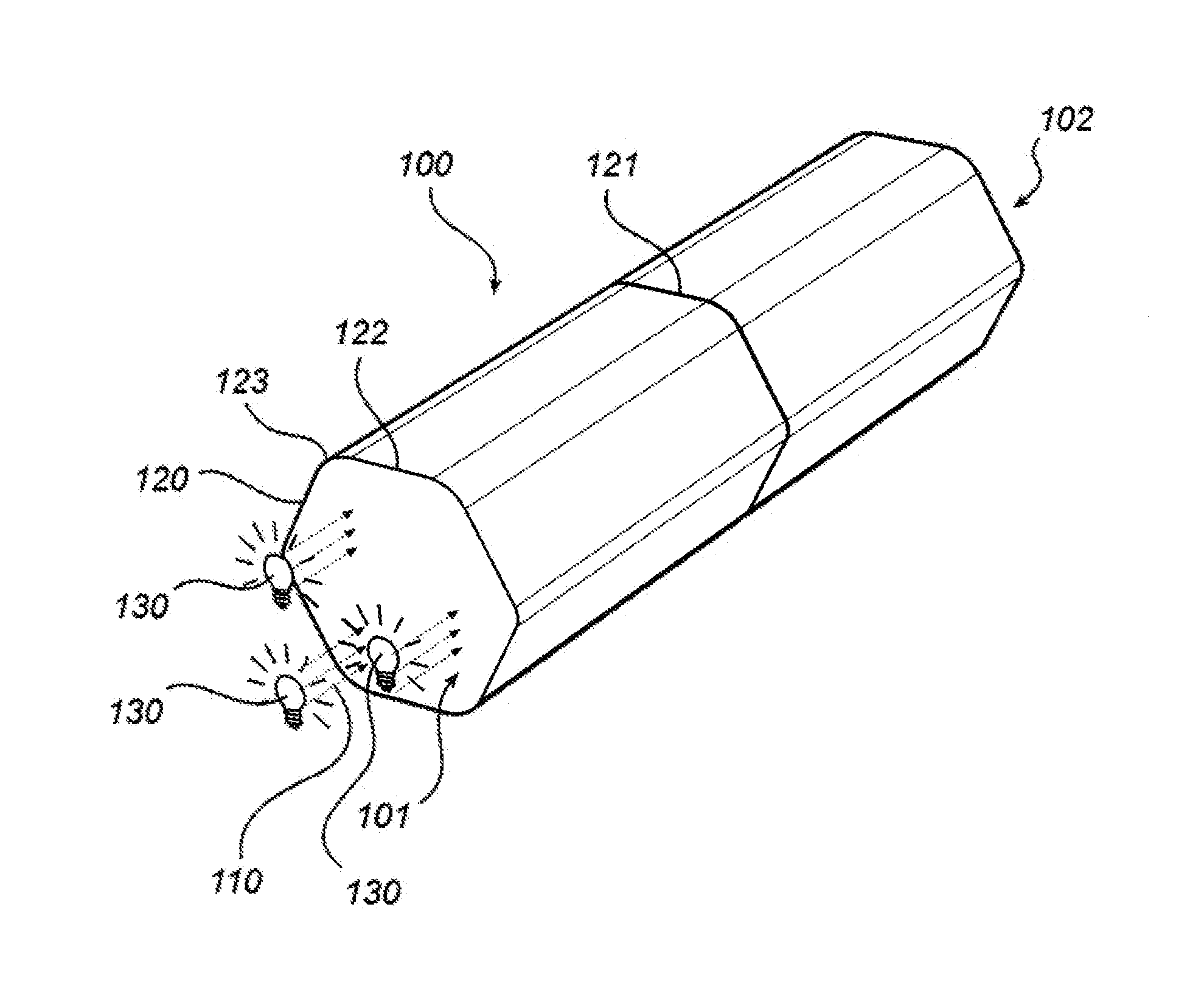
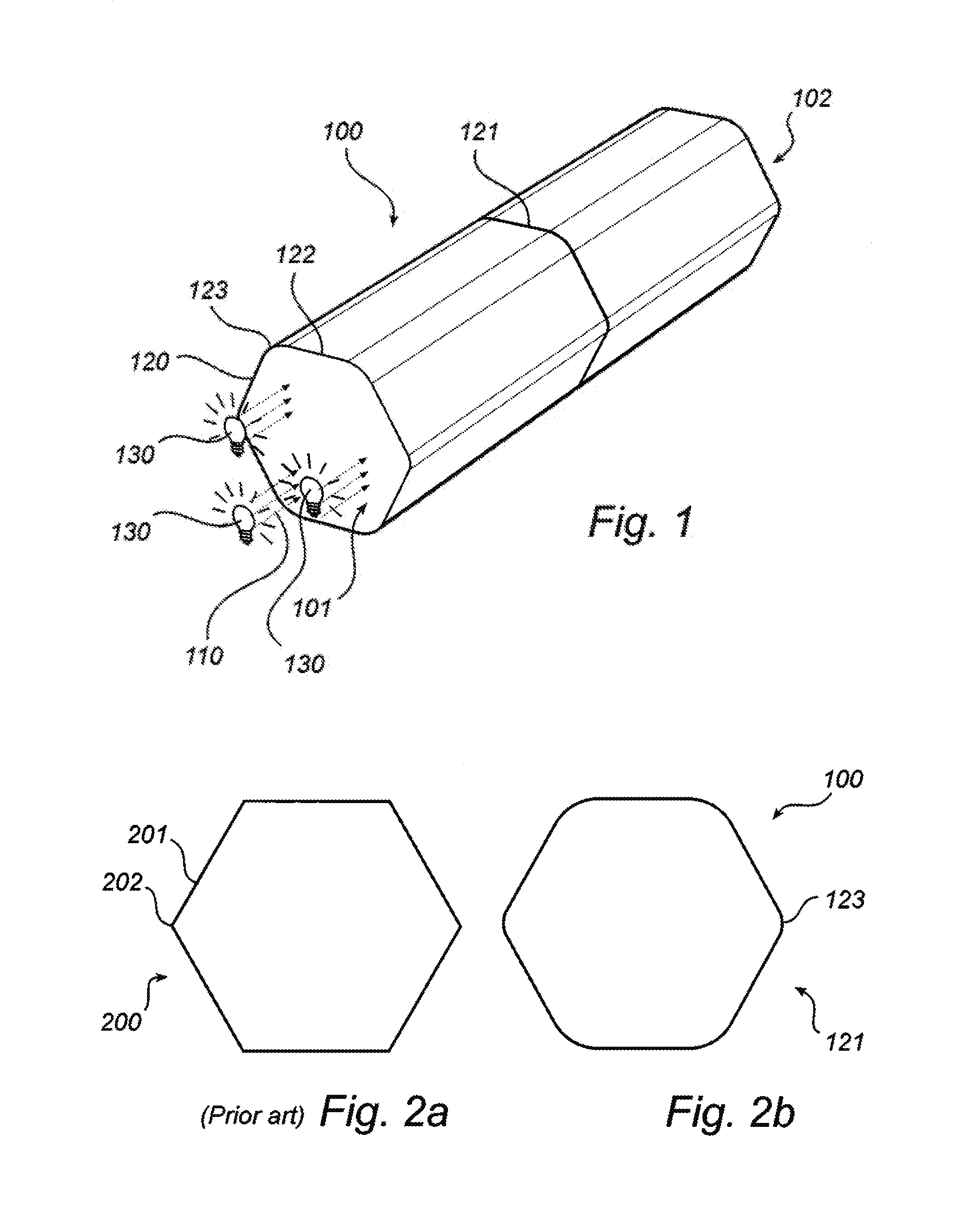
[0039]FIG. 1 is a schematic illustration of an elongated optical element 100. The optical element 100, which may be made of a transparent material like glass or plastic, is shaped as a cylinder and comprises a entry face 101 and an exit face 102. At operation, a bundle of light rays 110 is directed towards the entry face 101, wherein the bundle of light rays 110 undergoes total internal reflection (TIR) at the interfaces towards the surrounding medium. After being reflected within the optical element 100, the bundle of light rays 110 exits the optical element 100 through the exit face 102.

[0040]The contour of the optical element 100 in FIG. 1 is designed such that the perimeter 120 of a transversal cross-section 121 of the optical element 100 is defined by six edges 122 of zero curvature and six vertices 123 between any two adjacent ends of the edges 122. In the present embodiment, the edges 122 are of equal length and the vertices 123 are of equal length. The vertices 123 are segme...


PUM


Abstract

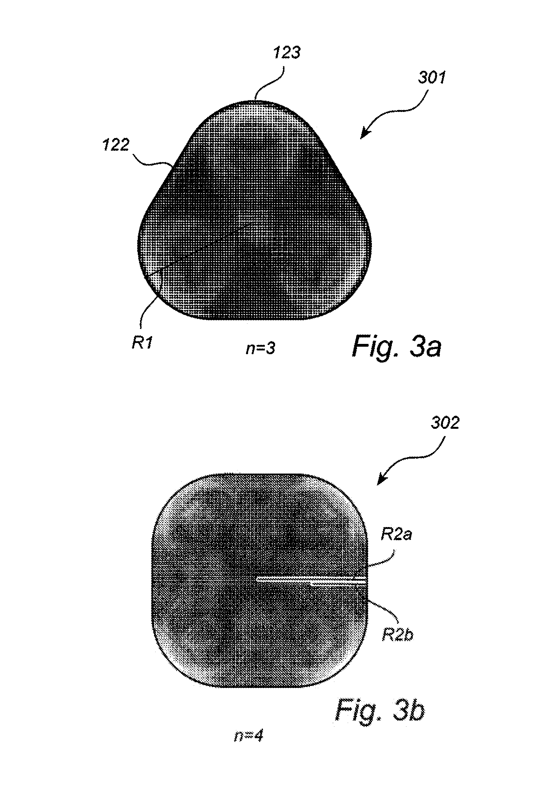
A method, an optical system and a lighting arrangement for homogenizing a bundle of light rays (110) by means of an elongated optical element (100) arranged for homogenizing light. The bundle of light rays is directed into a transversal entry face (101) of the optical element, and into at least one of the following geometrical regions: (a) a neighbourhood of the perimeter of the entry face; (b) a neighbourhood of at least a portion of a first line segment (R1) extending from the centre of the entry face to a mid-point of a vertex (123); (c) a neighbourhood of at least a portion of a second line segment (R2a) extending from the centre of the entry face to a midpoint of an edge (122).

Description

FIELD OF THE INVENTION[0001]The present invention generally relates to the field of optical components. More precisely, it relates to a method, an optical system and a lighting arrangement for homogenizing a bundle of light rays.BACKGROUND OF THE INVENTION[0002]Numerous systems in various fields of industry require a provision of a beam of light which is homogeneous (uniform) across the span of the light beam, in terms of properties such as a illuminance and / or colour. For example, in many medical applications such as laser therapy, laser bio-stimulation, and photo-dynamic therapy, it is highly desirable that the light beam has a homogeneous illuminance in the output profile of the light beam. As most light sources, however, emit a light which is non-homogeneous, light filtering and / or devices of light correction have been proposed to obtain the sought homogeneity of the light.[0003]In a case where the light is generated from a plurality of light sources (e.g. LEDs with different co...

Claims


Application Information

Patent Timeline
Patent Type & Authority Applications(United States)
IPC IPC(8): F21V8/00G02B27/09
CPCG02B6/0096G02B27/0927G02B6/4298A61N2005/063G02B27/0994
Inventor TUKKER, TEUNIS WILLEMIJZERMAN, WILLEM LUBERTUSGOORDEN, SEBASTIANUS ADRIANUS
Owner KONINKLIJKE PHILIPS ELECTRONICS NV
Learn More