

Methods to increase gasoline yield
a gasoline yield and gasoline technology, applied in the field of methods to increase the yield of gasoline, can solve the problems of unacceptably low yield of two-phase tar-aqueous mixture, unsatisfactory catalyst performance, and high cost, and achieve the effect of improving the amount of valuable fuel components
- Summary
- Abstract
- Description
- Claims
- Application Information
AI Technical Summary
Problems solved by technology
Method used
Image

Examples
example 1
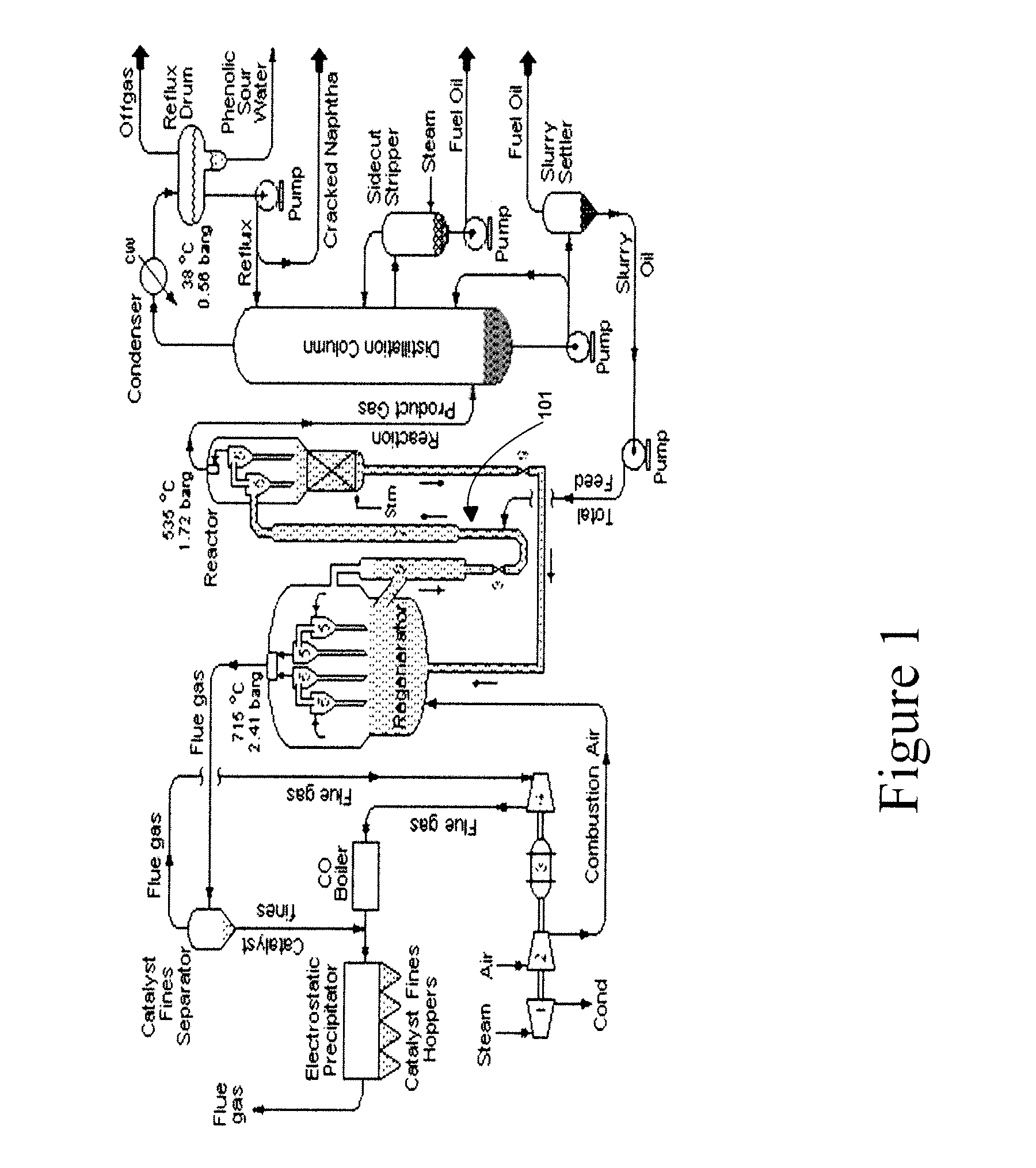
Testing Equipment
[0155]The co-processing of petroleum fraction feedstock with varying amounts of renewable fuel oil (RFO) (or the processing of the petroleum fraction feedstock alone as a comparator), were conducted in a Model R+ Kayser Technology Advanced Cracking Evaluation (ACE) FCC unit (herein referred to as “ACE testing unit” or “FCC unit”), using an FCC catalyst.
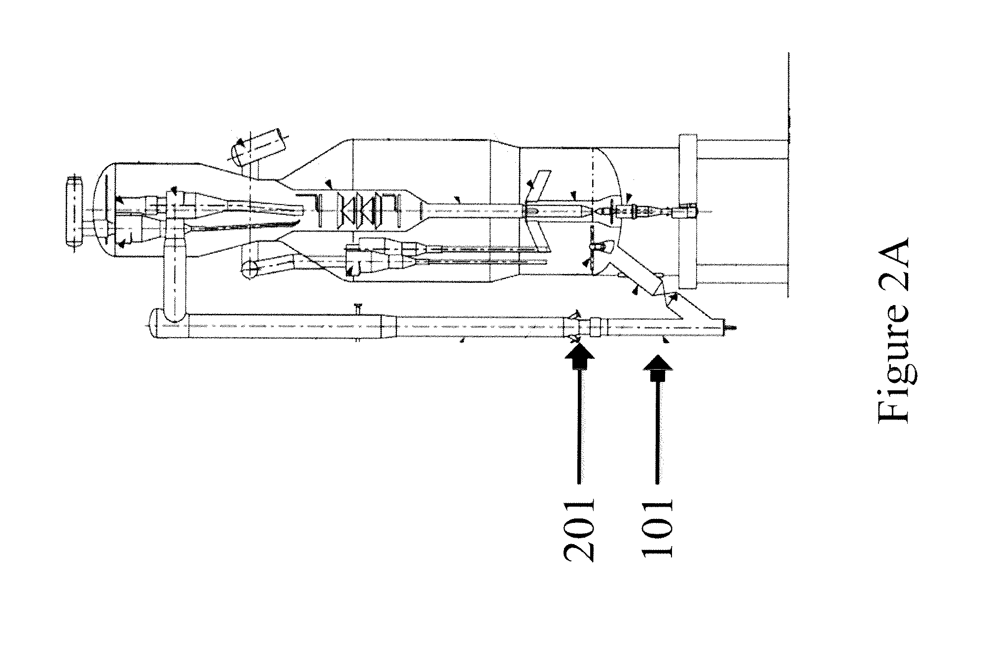
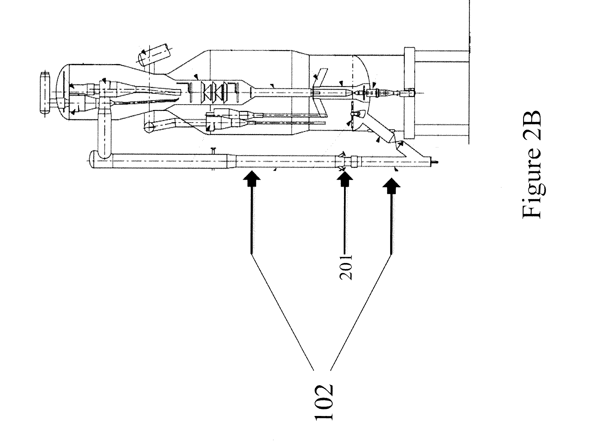
[0156]The ACE testing unit had hardware and software that enabled multiple runs to be accurately performed without operator intervention. The reactor consisted of a 1.6 cm ID stainless steel tube with a tapered conical bottom. A diluent (nitrogen), flowing from the bottom, fluidized the catalyst and also served as the stripping gas at the end of a catalytic run. The feedstock that was introduced in to the ACE testing unit to be cracked was fed from the top via an injector tube with its outlet tip near the bottom of the fluid bed. An injector position of approximately 2.86 cm, measured from the bottom of the reactor, w...
example 2
[0203]Testing Equipment: The co-processing of renewable fuel oil (RFO) with petroleum fraction feedstock (or the processing of the petroleum fraction feedstock alone as a comparator), was conducted in a fluid-bed Microactivity Test reactor (MAT) unit (herein referred to as “MAT testing unit”), using a commercially available equilibrium catalyst.
[0204]A biomass-derived liquid having properties similar to that shown in Table 1 was obtained from a commercial rapid thermal conversion plant where residual wood was thermally cracked at mild temperature in a short duration (typically less than 5 seconds) with about 70 to 80 wt. % liquid yield. A heavy gas oil (HGO) and a 5 wt. % RFO blend were cracked in a MAT testing unit at 510° C. (950° F.) with a constant oil injection time of 30 s using similar equilibrium catalyst as the case of Example 1.
[0205]In this example, dry gas is composed of H2, H2S, CO, CO2, and C1-C2 hydrocarbons. The dry gas yield increased exponentially with conversion. ...
example 3
[0213]A series of samples of a vacuum gas oil (VGO) and a 5 wt. % renewable fuel oil (RFO) blend were cracked in the MAT testing unit (reactor bed, Fluid-2) under similar conditions as in Example 2. The VGO employed in Table 2, labeled FHR CAT Feed, had a density of 0.9196 g / mL at 15.6° C. The RFO itself had a density of 1.198 g / mL, and a water content of 26.58 (wt. %). The 5 wt. % RFO in VGO blend employed in Table 3, labeled 5 wt % RFO in FHR CF, had a density of 0.9243 g / mL at 15.6° C. In 100 lbs of the 5 wt. % RFO in VGO blend employed the water content was about 1.329 lbs. The analysis, characterization, and results for the VGO samples are presented in Tables 2, 3 (on an as fed basis), and Table 4 (refinery flows summary), while the analysis, characterization, and results for the 5 wt. % RFO in VGO blend are presented in Tables 5, 6 (on an as fed basis), Table 7 (on a water-free feed basis), Table 8 (refinery flows summary) and Table 9 is a calculation of gallons of gasoline at...
PUM
| Property | Measurement | Unit |
|---|---|---|
| temperatures | aaaaa | aaaaa |
| residence times | aaaaa | aaaaa |
| residence times | aaaaa | aaaaa |
Abstract
Description
Claims
Application Information