System and process for reacting a petroleum fraction

a petroleum fraction and system technology, applied in the field of system and process for reacting petroleum fractions, can solve the problems of low hydrogen purity, co-current upflow design can be susceptible to solid accumulation, co-current upflow can suffer, etc., to achieve the effect of reducing the number of reactions

a petroleum fraction and system technology, applied in the field of system and process for reacting petroleum fractions, can solve the problems of low hydrogen purity, co-current upflow design can be susceptible to solid accumulation, co-current upflow can suffer, etc., to achieve the effect of reducing the number of reactions

US20090314686A1Inactive Publication Date: 2009-12-24UOP LLC

Image

  • System and process for reacting a petroleum fraction
  • System and process for reacting a petroleum fraction
  • System and process for reacting a petroleum fraction

Examples


Embodiment Construction

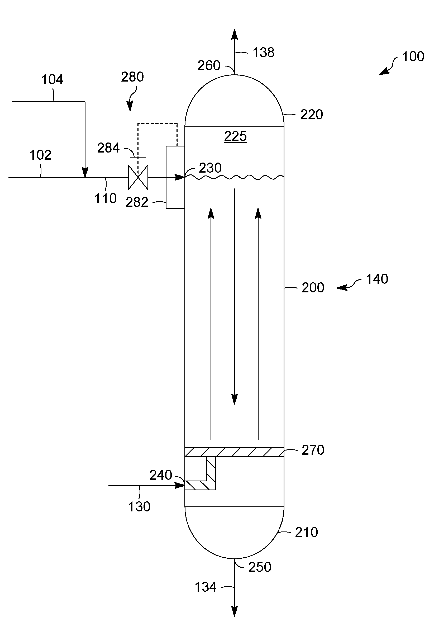
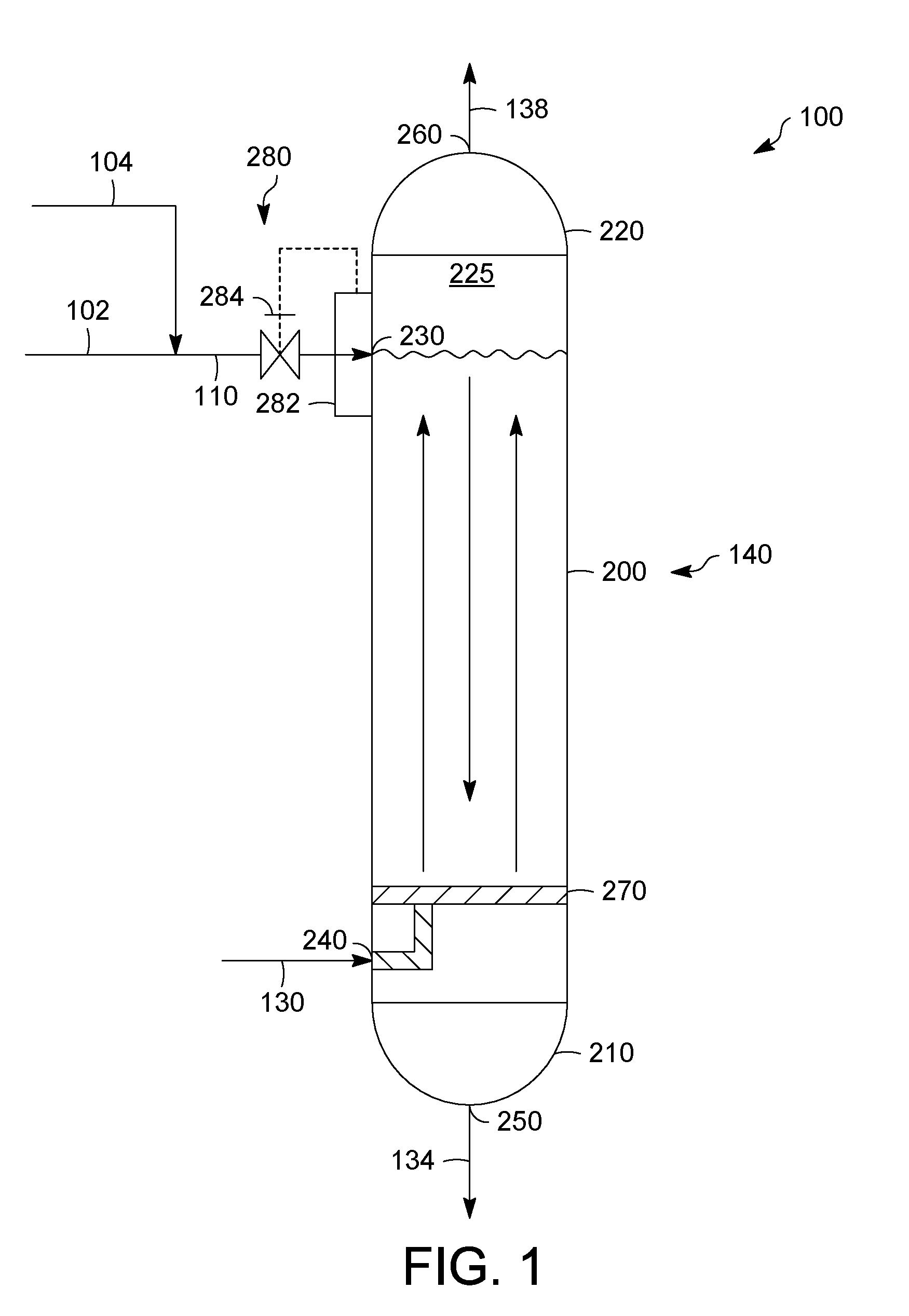
[0018]Referring to FIG. 1, an exemplary system 100 for hydrogenating one or more unsaturated aromatic and non-aromatic compounds, converting at least one hydrocarbon compound comprised in, e.g., pitch, and / or removing at least one of nitrogen and sulfur from one or more hetero-compounds in a petroleum fraction is depicted. The system 100 can include a bubble column reactor 200 that can receive a first feed 110 and a second feed 130. The first feed 110 can include a petroleum fraction stream 102 combined with one or more catalyst particles in a catalyst stream 104. A combination of the petroleum fraction stream 102 and the catalyst stream 104 can form a solid-in-liquid suspension as the first feed 110. Typically, at least about 90%, by volume, of the petroleum fraction stream 102 has a boiling point of at least about 300° C., desirably over about 520° C., and optimally over about 524° C., as determined by ASTM D-1160-06. The petroleum fraction stream 102 can include a vacuum residue,...


PUM


Abstract

In one exemplary embodiment, a system for reacting a first feed can include a petroleum fraction having at least about 90%, by volume, with a boiling point of at least about 300° C. The system can include a bubble column reactor. The bubble column reactor, in turn, can include a first inlet for the first feed and a second inlet for a second feed including a gas rich in hydrogen. In addition, the petroleum fraction may be in counter-current flow with respect to the gas rich in hydrogen inside the bubble column reactor.

Description

FIELD OF THE INVENTION[0001]This invention generally relates to a system and a process for reacting a petroleum fraction.DESCRIPTION OF THE RELATED ART[0002]Typically, a hydrocracking process is used in a large number of petroleum refineries. Such a process can be used to react a feed, such as a heavy crude oil residual fraction. In general, the hydrocracking process can split feed molecules into smaller molecules having a higher average volatility and a greater economic value. At the same time, a hydrocracking process can improve material quality by increasing the hydrogen to carbon ratio of the stream and by removing sulfur and nitrogen.[0003]In some hydrocarbon conversion processes, a slurry reactor or a bubble column reactor (hereinafter may be referred to as a bubble column reactor) receives feeds of a heavy crude oil residual fraction and a gas reactant, such as hydrogen. Generally, the heavy crude oil residual fraction is in co-current flow with the gas reactant inside the re...

Claims


Application Information

Patent Timeline
24 Dec 2009
Publication
US20090314686A1
IPC
C10G35/14
CPC
B01J8/1818; B01J8/22; B01J2208/0061; B01J2219/0004; C10G45/00; C10G45/56; C10G47/36; C10G2300/107
Inventors
ZIMMERMAN, PAUL R.